Kohs & Company Allegheny Скачать руководство пользователя страница 5

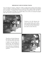
The photograph to the left shows the drawbar 

release hanging down under the operational 

buffer  assembly.    The  prototypical  double 

drawbar inserts into the two slots just above 

the release.

The Photograph to the right shows the 

battery wiring harness for the sound 

system  batteries.  The  connection  is 

color-coded for polarity, so pay close 

attention when plugging the harness 

into the coal bunker.

The photograph to the left shows the sound/

control system on/off switch under the cistern 

hatch.  The sound controls are accessed under 

the hatch to the right of the switch.

The image to the right illustrates the 

arrangement  of  the  sound  controls 

as  though  looking  through  the  cis-

tern hatch facing to the front of the 

locomotive.  The controls should be 

adjusted using a small plastic screw-

driver to prevent shorting the circuit 

board should you touch it during the 

adjustment.

Содержание Allegheny

Страница 1: ...to protect the finish This locomotive model is designed to operate on Direct Current DC electricity Any applica tion of Alternating Current AC WILL DESTROY THE INTERNAL ELECTRONIC COM PONENTS OF THIS...

Страница 2: ...t is not possible to incorrectly make these connections With the connection made the excess wire may be carefully pushed into the locomotive and tender When disconnecting the locomotive from the tende...

Страница 3: ...or an extended period or will be in storage it is highly recommended that the batteries be removed from the model To access the manual functions of the system the supplied system controller needs to b...

Страница 4: ...l System insert page included with these instructions Using high extremes on these controls is not recommended as severe distortion will result in the sound LOCOMOTIVE CARE AND MAINTENANCE Routine mai...

Страница 5: ...e attention when plugging the harness into the coal bunker The photograph to the left shows the sound control system on off switch under the cistern hatch The sound controls are accessed under the hat...

Страница 6: ...compatible with the current DCC tech nology and there are connectors on the internal circuit boards to interface with DCC decod ers For more specific information on this connection process please get...

Страница 7: ...dius curves if they are not properly aligned when the locomotive is placed in service The photo to the left illustrates the correct setup for the rocker units notice that the rocker head is centered o...

Страница 8: ...ook for the overlap in the plastic wrapping and carefully unwrap it from both units With the plastic removed undo the tape that secures the inner wrapping this will expose the model Use great care in...

Отзывы: