


Should you choose to use a less expensive power supply or one which does not meet the above
criteria, undesirable operating characteristics may result as well as possible damage to the
electronics used in the model. If you have questions regarding your selection, do not hesitate
to contact us for advise.
PREPARINg ThE SOUNd SYSTEM fOR OPERATION
The locomotive and tender contain a state-of-the-art sound/control/lighting system which digi-
tally recreates actual locomotive sounds, provides automatic and manual control of all lighting
functions and affords you automatic as well as manual control of the reverse-gear mechanism
all using standard DC track power. While this system requires track voltage to actuate certain
sounds and directional features, the actual power used to operate the system is supplied by
standard '9V' batteries that are placed in the tender coal bunker during the operation of the
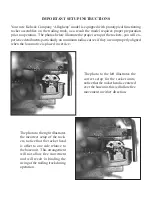
locomotive. There is a wiring harness packed in the box along with the locomotive and tender.
At the end of the wiring harness is a male plug which needs to be inserted into the receptacle
located in the coal bunker of the tender, with this connection made, the coal load can be placed
over the batteries to conceal their installation. When you unplug the batteries, do not pull on
the wires, only the plug shell.
Note: If the ON/OFF switch located under the tender cistern hatch is left in the on position
with the batteries installed, they will be drained whether the tender is connected to the locomo-
tive or not. If the locomotive will not be operated for an extended period or will be in storage,
it is highly recommended that the batteries be removed from the model.
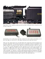
To access the manual functions of the system, the supplied system controller needs to be wired
in-line between your power supply and the track. There are four (4) screw terminals on the
bottom of the control box which are labeled 'To Track' and 'From Trans', these should be self-
explanatory, there are also 'A' and 'U' designations to allow you to align your polarity. There is
an included 9V wall transformer to supply power for the control box, you will see the receptacle
on the control box near where the wires for the transformer and track are connected.
OPERATING THE LOCOMOTIVE
The tender was shipped to you with a scale 'E' type coupler installed for display and opera-
tion. A Kadee unit may be substituted for the scale unit, the holes are pre drilled and tapped
for the installation. It is recommended that you operate the locomotive at a varying speeds
and in both directions during the break-in period, the break-in period should last for a total of
approximately 60 minutes (this may be accomplished on an incremental basis). This will help
the drive system to 'run-in' resulting in smoother running characteristics.
You are now ready to put the locomotive into operation. To activate the sound system, locate
the sound system switch under the water tank hatch. Shortly after turning the system on you
will hear the blowers activate. With the locomotive stationary you will hear, in addition to the
blowers, the air compressors and pressure relief valves on an intermittent basis. The whistle
and/or bell may be sounded at any time, when the system is turned on simply by touching the
appropriate control button once to turn it on and again to turn it off.


