


Remote & Electronic Fire Control Models – For Diagrams refer to Section 2
4.10
Removing the burner assembly from the fire.
4.10.1
Prepare work area (lay down dust sheets etc.)
4.10.2
Lift the fender and ash pan cover of the way and put them in a safe
location. Remove the loose coals from the fuel bed and front
ceramic rail. Remove the front ceramic from the rail. Unscrew the two
pozi-driv fixing screws which secure the burner heat shield and remove
it from the fire.
4.10.3
Isolate the gas supply and remove the inlet pipe from the appliance
inlet elbow. Unscrew and remove the four screws which retain the
burner. Remove the HT lead from the Pilot electrode and remove the
burner assembly from the fire, ensuring not to pull to tightly on the PCB
wiring. Cut the cable tie from the remote infrared eye self adhesive
pad, which will be situated on the hearth panel, flush with the front edge
of the ashpan cover.
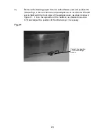
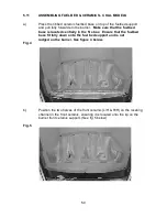
4.10.4
To refit the burner assembly. Ensure wiring is fitted correctly to the PCB
assembly. Push the base of the control panel fully into the fire and
secure with the four screws. Refit the gas supply pipe and carry out a
gas tightness test. Refit the burner heat shield then refit the coals /
referring to section 3 for the correct coal layout. On RC models the
infrared eye must be cable tied back to the self adhesive pad which will
be situated on the hearth panel. The fender and ash pan cover or can
now be re-positioned.
4.11
Removing the Valve Assembly
4.11.1
Remove the burner assembly as in section 4.10
4.11.2
Remove the thermocouple retaing nut from the valve. remove the
main pipe, inlet pipe and pilot pipe from the valve.
4.11.3
Remove the valve retaining screws and remove. Re-assemble in
reverse order and carry out a gas tightness test. Re-fit coals
as shown in section 3. The fender and ash pan cover can now be
re-positioned.
4.12
Removing the Pilot Assembly.
Note : Because this appliance is fitted with an atmosphere sensing ‘Oxy-
Pilot’ it is not possible to replace the thermocouple separately, because the
thermocouple position is factory set to a tight tolerance. Any replacement of
parts on the pilot requires a complete new pilot assembly.
37


