KGC-1
Chapter 5
Operation Manual
Operation
Chapter 5 Operation
5.1 Panel layout and operating switches
POWER lamp
ALARM lamp
DATA
lamp
POWER switch
MODE switch
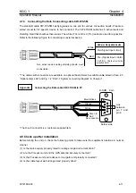
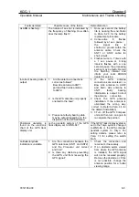
Fig. 5.1 Panel layout on the Processor unit
5.1.1 POWER switch
This switch is used to turn on and off the GPS Compass unit.
5.1.2 MODE switch
This switch is used to change the type of data and its update rate. The relation of the data type and the
switch number is shown in Para 5.3.
5.1.3 POWER lamp
The POWER lamp turns on when the POWER switch is pressed to energize the unit. The lamp goes
off when the POWER switch is pressed again to turn the unit off..
5.1.4 ALARM
lamp
The ALARM lamp blinks when an abnormal condition is detected in the unit as a result of
self-diagnosis check-up. The possible fault conditions include; running out of the back-up battery
capacity, a shorted antenna cable, etc. According to the nature of a faulty condition, the lamp blinks at
a different interval I(The mark and space ratio to be modified) (For detail, please refer to Chapter 6
“Maintenance” and Para 6.2.2 “Trouble shooting.”)
5.1.5 DATA
lamp
The DATA lamp starts to blink when the unit is set ready to output the navigational data. The lamp
lighting becomes stationary when the bearing data is ready to be output.
93121652-00
5-1


