KGC-1
Chapter
4
Operation Manual
Installation
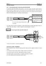
4.7 Connecting the units
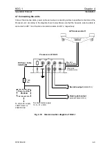
Connect the Antenna cable, power cable and various connecting cables to specified connectors at the
Processor unit, according to the diagram shown below. Make sure that the bow side antenna cable is
connected to ANT 1 and the stern side antenna cable to ANT 2, respectively.
GPS Antenna GA-11
Fig. 4.10 Interconnection diagram of KGC-1
Processor unit KGC-1
Nav data output
(NMEA0183)
Bearing data output
(NMEA0183/IEC61162)
DC Power Cable
CW-255-2M
To ship’s mains supply
10.8 ~ 31.2 VDC
To ship’s AC supply
100/115 VAC or,
200/230 VAC
Power rectifier
Bow side
Antenna cable
Stern side
Antenna cable
PS-003A
Fuse
(3A)
93121652-00
4-9

