6
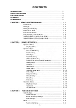
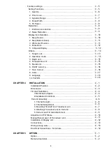
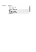
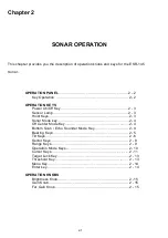
Function settings……………………………………………………………………
3 - 5
Setting Functions
…………………………………………………………………
1.
Gain Up………………………………………………………………………..
2.
TVG Curve………….…………………………………………………………
3 - 5
3 - 6
3 - 7
3.
Dynamic Range……….………………………………………………………
3 - 7
4.
Pulse Width………………….…………………………………………………
3 - 8
5.
TX Power……………………………………………………….…….………..
3 - 8
Reduction
………………………………………………………………..…………
1. Interference reduc
tion……………………………………………………..…
2.
Noise Reduction…. ………………………………………………….............
3 - 9
3
– 9
3 - 9
Display Item Selection
……………………………………………………..….....
3 - 10
1.
Step (Sonar)…………………………………………………………..….……
3 - 10
2.
Step (Bottom Scan)….. ……………………………………………..……....
3 - 11
3. Off-
Center Position...………………………………………………………....
3 - 11
4. Scale Dots
…………………………………………………………….……….
3 - 12
5.
Compass Display……………………………………………………..………
3 - 12
Others
…………………………… ………………………………………….……...
3 - 13
1. T
arget Lock…………………………………………………………………....
3 - 13
2.
Operation mode……………………………………………………….……...
3 - 15
3. Depth unit
………………………………………………………………….......
3 - 15
4. Temperature unit
……………………………………………………………....
3 - 15
5. Speed unit
……………………………………………………………………..
3 - 15
6. HOIST Auto Up
……………………………………………………….……....
3 - 16
7.
Train Correct……………………………………………………………..……
3 - 16
8.
Color……………………………………………………………………..…....
9. L
anguage………………………………………………………………….….
10. FILTER
………………………………………………………………….…..
3 - 17
3 - 18
3 - 18
CHAPTER 4
INSTALLATION
…………………………………………………………. 4 - 1
Installation Po
sition…………………………..……………..………….…….
4 - 2
Dimensions……………..………………………….……………………..….…
4 - 3
TD tank Installation
………………………………………………………..…...
4 - 4
1.Maintenance
Space…….…….…………………………………………
4 - 4
2.Installation Con
ditions…………………………………………….…….
4 - 5
Hull unit Asse
mbly…………………………………………………….………
4 - 6
1. TD shaft Len
gth………………………………………………………...
4 - 6
2. TD shaft Adj
ustment……………………………………………………
4 - 6
3. Mounting TD shaft into Transducer unit.
……………………………..
4 - 7
4. Attaching Transducer unit to Hull unit
…………………………….….
4 - 8
5. Hull unit and TD tank Attac
hment………………………...…………..
4 - 9
Adjustment of TD
Stroke……………………………………………….……..
4 - 10
Manual Raise/Lower
of Transducer unit..………………………….….……
4 - 11
Installation of Display unit……………………………………………….……
4 - 12
Connections.……………………………………………………………………
4 - 13
Wiring among unit
s.…………………………………………………….……..
4 - 13
Electrical Connections -
Terminals………………..………..………….……
4 - 14
CHAPTER 5
OPTION
…………………………..……………………………………...... 5 - 1
Option………………………………………..……………………..…..…..…..
5 - 2
Remote
Controller………………………………………..………….….……..
5 - 2
Содержание ESR-145
Страница 1: ......
Страница 2: ......
Страница 3: ......
Страница 4: ......
Страница 6: ... This page intentionally left blank ...
Страница 14: ...8 This page intentionally left blank ...
Страница 59: ... This page intentionally left blank ...
Страница 62: ...4 3 INSTALLATION DIMENSIONS HULL UNIT DISPLAY UNIT Unit mm inch ...
Страница 75: ... This page intentionally left blank ...
Страница 85: ......
Страница 86: ......


