background image

CVS-833/833C 

                Chapter 6


Using the Menu


93132902-00 


6-15 

6.11.2 DEPTH RANGE PRESET 

Registers the depth ranges to be allocated to the depth numbers, which is selected by the rotary range 

switch. The selectable range tables are shown below depending on the sounder type number and the 

depth unit. 


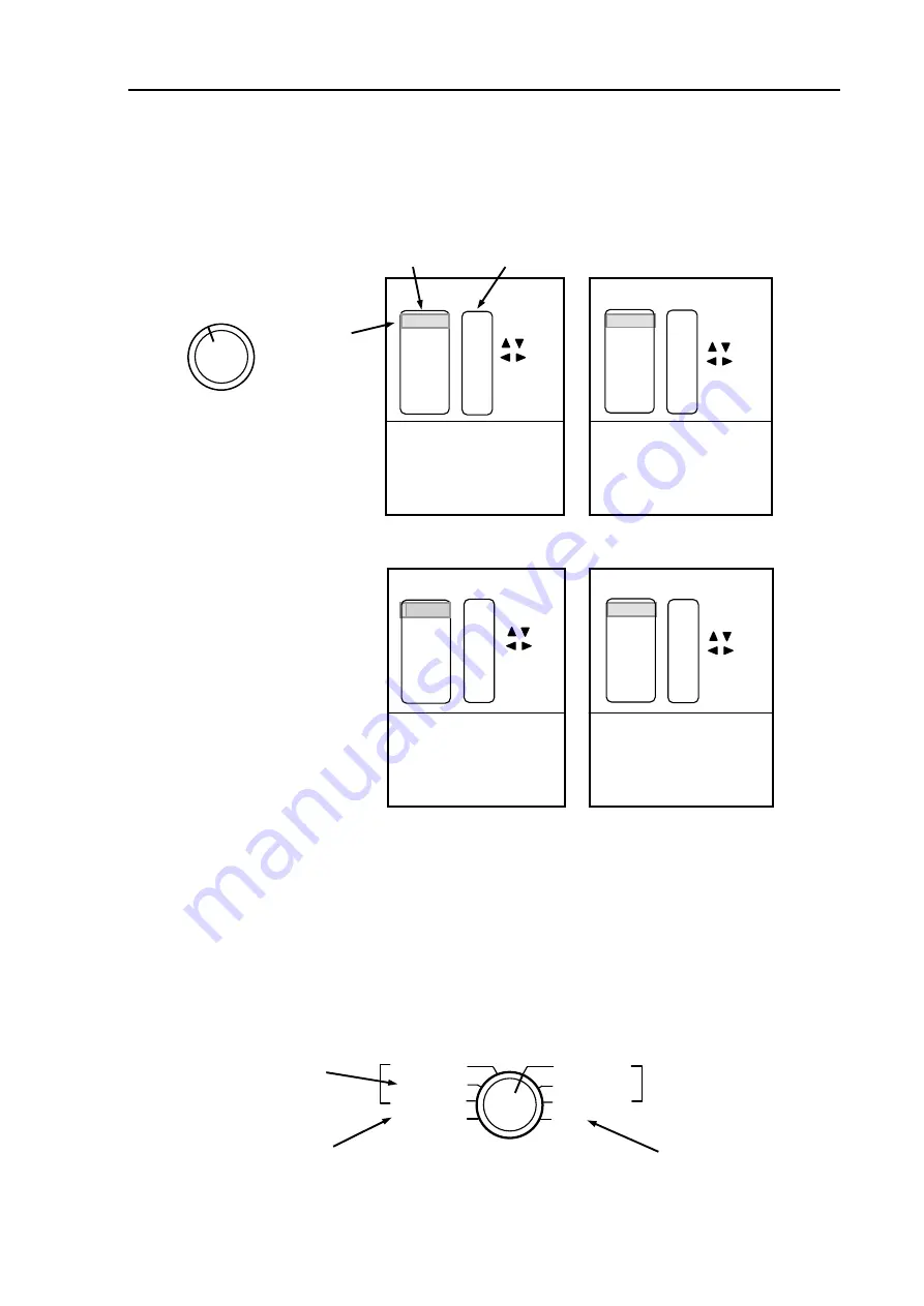
6.11.3 IMAGE MODE SETTING 

Changes various split screen displays, which can be selected by the rotary control switch. 

NORM/BTM (Normal / Bottom) 

DUAL FREQ (Dual Frequency) 

MIX  


Selected range 

Range depth number 

RANGE 

3 6 

4 5 

m (meter) / J.fm(Japanese fathom)   
/ fm(fathom)/ l.fm (Italian Fathom)

35 
65 

120 
300 
600 
900 

25 
55 
90 

200 
500 
800 

10 
40 
70 

140 
350 
650 

15 
45 
75 

160 
400 
700 


20 
50 
80 

180 
450 
750 

30 
60 

100 
250 
550 
850 

1000  1100  1200 

2 DEPTH  RANGE  PRESET 


RANGE 1

      5 

RANGE 2 

    10 

RANGE 3 

    20 

RANGE 4 

    50 

RANGE 5 

  100 

RANGE 6 

  200  

RANGE 7 

  500 

RANGE 8 

  1000 

:  Sel 
:  Mod 
 

MENU : Exit

[m] 

10 

120 
280 
520 

1400 
2600 
3800 

100 
240 
480 

1200 
2400 
3600 

60 

180 
400 
800 

2000 
3200 

20 

140 
320 
560 

1600 


 1
 3000 

40 

160 
360 
600 

800 

2800
4000

80 

200 
440 

1000 
2200 
3400 

:  Sel 
:  Mod 
 

MENU  :  Exit

[ ft ] 

2 DEPTH  RANGE  PRESET 


RANGE 1

      10 

RANGE 2 

    20 

RANGE 3 

    40 

RANGE 4 

    100 

RANGE 5 

    200 

RANGE 6 

    600   

RANGE 7 

  1000 

RANGE 8 

  2000 

For CVS-833C 

Figure 6.20 DEPTH RANGE PRESET menu 

m (meter) / J.fm(Japanese fathom)   
/ fm(fathom)/ l.fm (Italian Fathom) 

2 DEPTH  RANGE  PRESET 


RANGE 1

      10 

RANGE 2 

    20 

RANGE 3 

    40 

RANGE 4 

    60 

RANGE 5 

  100 

RANGE 6 

  200  

RANGE 7 

  400 

RANGE 8 

  600 

:  Sel 
:  Mod 
 

MENU  :  Exit 

100 
240 
480 

1200 


60 

180 
400 
800 

2000 

20 

140 
320 
560 

1600  1

40 

160 
360 
600 

800 

80 

200 
440 

1000 


10 

120 
280 
520 

1400 


[ ft ] 

ft (feet) 

For CVS-833 

2 DEPTH  RANGE  PRESET 


RANGE 1

      5 

RANGE 2 

    10 

RANGE 3 

    20 

RANGE 4 

    30 

RANGE 5 

    50 

RANGE 6 

    80   

RANGE 8 

  100 

RANGE 7 

  200 

30 
60 

100 
250 
550 

20 
50 
80 

180 
450 

15 
45 
75 

160 
400 

10 
40 
70 

140 
350 

25 
55 
90 

200 
500 

35 
65 

120 
300 
600 

[m] 

:  Sel 
:  Mod 
 

MENU : Exit

Cursor 

(HF) 

NORM/ZOOM 
NORM/BTM 
NORMAL  
MIX


IMAGE MODE SWITCH

(LF) 

NORM/ZOOM 

NORM/BTM 


NORMAL 

DUAL FREQ 


(1) 

ft (feet) 

(2) 

(3) 

Содержание CVS-833

Страница 1: ......

Страница 2: ...ain Power It is still possible to receive an electric shock caused by unintentionally switching on the power during repair work To prevent this from happening make sure to completely disconnect the unit from the ship s main supply before attempting any inspection z Dust Dust can accumulate inside after long periods of use Allergies can result from the inhalation of this dust therefore during inspe...

Страница 3: ...gnoring this sign may lead to injury to the human body or damage to the equipment Alarm Caution mark To handle the equipment ignoring this sign may lead to a malfunction of the equipment Caution Warning High Voltage mark To handle the equipment ignoring this sign may lead to electrical shock to the human body Prohibition mark This sign indicates that a specified action is prohibited The prohibited...

Страница 4: ... overview the whole of the contents as well as refer to detailed information for your specific requirement Chapter 1 General information General Applicable standard Type name of component units Software type used System configuration Chapter 2 Equipment composition Standard equipment list Spare parts list Installation material list Optional items list Chapter 3 Specification Functional Specificati...

Страница 5: ...on Chapter 5 Basic Operation Introduction Theory of fish finder operation Operating panel layout Getting started Selecting image mode Registering the depth to the range numbers Setting the receiver gain Shifting the image Measuring the depth by VRM Changing the image scroll speed Setting up the alarm Chapter 6 Using the menu Available menus How to use the Menu Exiting from the Menu Menu1 Menu2 Men...

Страница 6: ...ed for service Self check function Trouble Shooting Chapter 8 Maintenance Periodic inspection and cleaning Chapter 9 Technical References Serial input data Details of input sentences Serial output data Data input output serial line Data input serial line 93132902 00 5 ...

Страница 7: ...General information Chapter 1 General information Contents Page No 1 1 General 1 1 1 2 Applicable standard 1 1 1 3 Type name of component units 1 1 1 4 Software type used 1 1 1 5 System configuration 1 1 93132902 00 Contents ...

Страница 8: ... the AUTO key the unit is set to hands free operation in which the gain and depth range are automatically selected to an optimized level by an internal micro controller chip 1 2 Applicable standard The CVS 833 833C is designed and tested to comply with the international standard of IEC 60945 3rd edition that defines the general requirements of electronic maritime equipment 1 3 Type name of compone...

Страница 9: ... 2D8 Temperature sensor ST 80 90 100 Other sounder Display CVS 833 833C AC DC Rectifier Type PS 003A Option DC Power cable CW 205 1 2M Transducer 50 200 KHz 10 8 31 2VDC 100 115VAC 200 220VAC NOTE Consult KODEN for a suitable cable type Figure 1 1 System configuration of CVS 833 833C 1 2 93132902 00 ...

Страница 10: ...CVS 833 833C Chapter 2 Equipment composition Chapter 2 Equipment composition Contents Page No 2 1 Standard equipment list 2 1 2 2 Essential option 2 2 2 3 Optional items list 2 2 93132902 01 Contents ...

Страница 11: ...W CVS 833C 1kW With mounting bracket and fixing knobs 3 5 kg 1 2 Hard cover C23MB41032 1 3 Hood C23MB41102 1 2 DC Power cable CW 205 1 2M 2 pin connector on one end and fly leads on the other 2m 1 3 Fuse F 7161 5A Normal blow Mains supply protection φ6 3 x 32 2 4 Truss tapping screw TPT5 x 20U Installation material For the display installation 4 5 Operation manual 93132902 1 0093132902 02 2 1 ...

Страница 12: ...ation Material Plastic A connecting cable attached 0 3kg ST 90 For the through hull installation Material plastic A connecting cable attached 0 5kg ST 100 For the through hull installation Material zinc bronze A connecting cable attached 1kg 2 Connecting cable CW 60 10M A BNC Connector on one end crimp terminals on the other 10m CW 153A 5M 6 pin connectors on both ends 5m CW 154A 5M 6 pin connecto...

Страница 13: ...ification Chapter 3 Specification Contents Page No 3 1 Functional Specification 3 1 3 2 Serial data 3 2 3 3 Power supply requirements 3 2 3 4 Environmental condition 3 2 3 5 External dimensions and weight 3 3 93132902 00 Contents ...

Страница 14: ...th is 600 meter Japanese fathom fathom Italian fathom 1 step space CVS 833C deepest displayed depth is 4000 feet 5 step space deepest displayed depth is 1200 meter Japanese fathom fathom Italian fathom 1 step space Picture Mode H high frequency normal L low frequency normal M Mix The above side by side display can be changed to vertical split or horizontal split screen The above picture modes are ...

Страница 15: ...Type NMEA0183 Ver 2 0 1 5 Sentence GGA GLL GNS GTD VTG MTW Output data Type NMEA0183 Ver 2 0 Sentence DBS DBT DPT MTW VHW GGA 3 3 Power supply requirements Input voltage 10 8 31 2 VDC Input power CVS 833 25W CVS 833C 30W measured at 24 VDC AC operation The AC DC rectifier type PS 003A is required Input voltage range 115 VAC or 230 VAC Input power requirement 220 W 3 4 Environmental condition 1 Tem...

Страница 16: ...ation 3 5 External dimensions and weight External dimensions Width x Height x Depth External dimensions 241mm x 238mm x 123mm Weight 3 5 kg 7 7lb Front side Figure 3 1External dimensions of the Receiver Indicator unit 93132902 01 3 3 ...

Страница 17: ...ach component of the system 4 1 4 3 Inspection of each component unit and accessories 4 1 4 4 Positioning the units 4 1 4 5 Cable routing and connections 4 1 4 6 Display installation 4 2 4 6 1 Table mounting 4 2 4 6 2 Flush mounting 4 3 4 6 3 Connections to CVS 833 833C 4 4 4 7 Check after installation 4 6 93132902 01 Contents ...

Страница 18: ...ollowing factors must be considered 1 The display unit should be positioned in the location where the external situation can be viewed 2 Locate the display so that it provides easy viewing from all likely operator s positions 3 Select a position safe and free from dampness water spray rain and direct sunlight 4 Provide enough space for servicing Consider access to the rear panel for connecting var...

Страница 19: ...e display unit to the mounting bracket 2 Remove the display unit from the bracket and place it on a flat and safe area 3 Place the mounting bracket to the place where the display unit is to be installed and fix the bracket with four 4 tapping screws 4 Reset the display unit on to the bracket and fix it using the two screws that were removed in step 1 Figure 4 1 Fitting the display unit in the tabl...

Страница 20: ...lastic screw covers which are fitted on each corner of the display front face 4 Put the display on the opening and fix with four 4 tapping screws In case you use M4 screws to fix the display select an appropriate screw length that best suits fixing the unit to the panel thickness 5 Refit the coverings removed in step 3 Figure 4 2 Flush mounting arrangement Figure 4 3 Flush mounting arrangement 931...

Страница 21: ...y 10 8 31 2 VDC J2 SER DATA Navigator connection 6 pin J4 TRIDUCER SPD TEMP Transducer with Water temperature speed sensor connection 8 pin J5 TD Transducer connection 3 pin Figure 4 4 Sounder connections GPS Navigator KGP Decca Navigator DR Loran C Navigator LR DECCA Navigator DR Loran C Navigator LR GPS Navigator KGP Junction Box JB 12 CW 60 154A CW 60 CW 60 154A 376 CW 154A CW 153A 155 CW 155 C...

Страница 22: ... 3 4 5 J3 EXT F F Pinout Signal name Remarks 1 EXT TRIG Sync trigger input from external sounder 2 GND Ground 3 Zero TRIG OUT Zero trigger output 4 NC 5 NC 1 3 J5 TD 2 Pinout Signal name Remarks 1 TD1 Transducer signal IN OUT 2 TD SH Transducer signal Shield 3 TD0 Transducer signal IN OUT 1 6 2 3 4 5 7 8 J4 TRIDUCER SPD TEMP Pinout Signal name Remarks 1 SPD Pulse Speed pulse input 2 SPD B DC suppl...

Страница 23: ...urning the CVS 833 833C on be sure to check the following items for proper device operation 1 Is the main supply properly rated for voltage and current 2 Is the connection between the display unit and sounder unit correct 3 Is the cable routing properly done 4 6 93132902 01 ...

Страница 24: ...LF 5 7 5 5 1 4 NORM ZOOM HF LF 5 8 5 5 1 5 MIX 5 8 5 5 2 Image scroll directions 5 8 5 5 2 1 DUAL FREQ 5 8 5 5 2 2 NORMAL 5 9 5 5 2 3 NORM BTM HF 5 9 5 5 2 4 NORM ZOOM HF 5 9 5 5 2 5 NORM ZOOM LF 5 10 5 5 2 6 NORM BTM LF 5 10 5 5 2 7 MIX 5 10 5 5 3 Displaying Dual Frequency image 5 11 5 5 4 Displaying Zoomed Sea bottom 5 11 5 5 4 1 Displaying Bottom Lock BTM image 5 11 5 5 4 2 Displaying Bottom Di...

Страница 25: ...O GAIN function 5 16 5 8 Shifting the image 5 16 5 8 1 Setting Fix Shift mode Selecting depth range and Fix Shift position 5 16 5 8 2 Displaying Auto Shift image 5 17 5 9 Measuring the depth by VRM 5 17 5 10 Changing the image scroll speed 5 18 5 11 Setting up the alarm 5 18 Contents 2 93132902 00 ...

Страница 26: ...h is sent to the transducer to transmit ultrasonic sound energy to the ocean The transmitted energy hits the school of fish or sea bottom and bounces back following the same path to the transducer The received signals are converted to electrical signals and subject to signal processing to allow a color presentation on the Liquid Crystal Display LCD When the ship moves from Point A to Point B the u...

Страница 27: ... sounder image various data including own ship s position speed temperature distance traveled and the sea bottom depth are shown on the screen These data can be deleted if required Transmitting line Echoes of the Sea bottom Ship s position Ship s Bearing Ship s speed Water temperature Depth XXXX XXX XX XXXX XX X XX X XX Xkt XX XX XXXX Reflections from the sea surface Echoes of a fish school Figure...

Страница 28: ... Gain Control and Image Mode change allowing quick and effective operations Tactile keypads are provided for additional settings and operations 5 3 1 1 The functions of various key switches and controls Power Brilliance controls T WER OFF urns the power on and off and also controls screen brilliance The brilliance increases when the control is turned clockwise and decreases when turned counter clo...

Страница 29: ...epth range 6 200 ft 600 ft Depth range 7 400 ft 1000 ft Depth range 8 600 ft 2000 ft Setting auto range Always displays the entire sounder image from the sea surface to the bottom To select this mode 1 Select Auto Range in Menu 6 2 Press the AUTO key repeatedly until AUTO appears Gain controls 0 2 3 6 7 4 GAIN LF 5 8 1 9 10 2 10 9 8 7 1 0 GAIN HF 5 6 3 4 GAIN HF Controls the high frequency receive...

Страница 30: ...y mode VRM moves one display to the other as long as either the UP or DOWN arrow key is pressed 1 Press the key to stop the sounder image 2 Press the key again to display the image scroll speed set up screen 3 Press the VRM up arrow or down arrow key to set up the speed Default 1 1 Alarm key Right arrow key Scroll speed Slow 1 32 1 16 1 8 1 4 1 2 1 1 2 1 Fast Each press of this key toggles the ala...

Страница 31: ...UAL FREQ Dual frequency display in normal screen 2 NORMAL Normal single screen with High frequency or Low frequency display 3 NORM BTM Split screen with Normal and Bottom Zoom display 4 NORM ZOOM Split screen with Normal and Partially Zoomed display 5 MIX Mixed High and Low frequencies image and normal High frequency image POWER OFF BRIGHTNESS Turning the power ON BRIGHTNESS Turning the power OFF ...

Страница 32: ... H L 5 5 1 2 NORMAL HF LF Displays a dual frequency images in normal mode 50 KHz at the left side and 200 KHz at the right side A single screen of High Frequency 200 KHz or Low Frequency 50 KHz image Normal Dual frequency Picture scrolls from right to left 5 5 1 3 NORMAL BTM HF LF Displays normal display High or Low selected by the Image Mode switch on the upper half and bottom zoom display on the...

Страница 33: ...layed in red In the mixed mode picture the high and low frequency images appear in the same position are mixed and displayed in a mixed color Mixed image Comparison High frequency images 5 5 2 Image scroll directions The following figures show all available displays in each mode Arrow marks show the image scroll direction The item with an asterisk indicates default picture mode 5 5 2 1 DUAL FREQ I...

Страница 34: ...ne way scroll ZOOM Bottom Zoom ZOOM NORM ZOOM HIGH ZOOM HIGH NORM High frequency Normal Image ZOOM Sea bottom fixed zoomed or Sea bottom sediment zoom NORM ZOOM Open Menu7 and select the BTM Zoom image The Bottom Zoom image is shown in a single display HIGH ZOOM NORM ZOOM ZOOM HIGH ZOOM NORM 5 5 2 4 NORM ZOOM HF NORM ZOOM Horizontally split one way scroll ZOOM NORM Vertically split one way scroll ...

Страница 35: ...scroll ZOOM NORM Horizontally split one way scroll NORM ZOOM NORM ZOOM Vertically split one way scroll LOW ZOOM ZOOM LOW ZOOM NORM NORM Low frequency Normal image ZOOM Bottom Lock image or Bottom Sediment Zoom image NORM ZOOM ZOOM Bottom Zoom Open Menu7 and select the BTM Zoom image The Bottom Zoom image is shown in a single display 5 5 2 7 MIX MIX H Vertically split one way scroll MIX HIGH MIX HI...

Страница 36: ...age mode registration For setting detail refer to Para 6 11 3 Image mode selection 2 Turn the MODE selection switch to select the DUAL FREQ mode Dual screen display will be shown Low frequency image High frequency image Vertical split Figure 5 6 Dual Frequency image display 5 5 4 Displaying Zoomed Sea Bottom The bottom zoomed screens are available in three kinds Sea Bottom Fixed Zoom Sea Bottom Se...

Страница 37: ...ock BTM image display 5 5 4 2 Displaying Bottom Discrimination B D image Similar to the NORMAL ZOOM mode the sea bottom is always shown flat with normal image shown in the upper half of the screen This allows easy viewing of fish schools near the sea bottom This feature also allows analysis of the sea bottom in addition to the type of fish school Refer to the following figure for detail To use thi...

Страница 38: ... depth scale so you can closely observe schools of fish near the bottom To use this function 1 Open Sub Menu 1 and select Zoom range Para 6 4 1 to set up a zooming range 2 Open Sub Menu 7 and select BTM Zoom Refer to Para 6 10 1 BTM Zoom The color of the letters BZ will turns to yellow 3 Turn the MODE selection switch to NORM BTM of either Low or High frequency Depth markers Zoomed depth range Fig...

Страница 39: ...tilizing this characteristic detection of small fish like anchovy sardines can be made possible by combining and processing signals of high and low frequencies reflected from the same object The MIXED image can be selected from COMPARISON or SUBTRACTION To use this function 1 Select COMPARISON or SUBTRACTION from Sub Menu 4 Refer to Para 6 7 5 for detail 2 Set the MODE control to MIX 5 6 Registeri...

Страница 40: ...6 1 Displaying Auto Range This function provides the entire sounder screen display from the sea bottom to the sea surface even if the sea bottom depth changes To use this function 1 Press the AUTO key repeatedly until the letters AUTO appears 5 7 Setting the receiver gain Turn the HIGH or LOW frequency gain control to make the sea bottom display turn red This setting gives good fish detection capa...

Страница 41: ...x Shift position In this mode sounding range can be determined by setting an upper depth line and the depth range The image starts from the upper depth line To use this function 1 Register the depth range Refer to 6 11 2 Registering depth range for detail 2 Select the depth range by the RANGE switch 3 Press the and key at the same time to set up shift positioning status 4 Press the or key to set t...

Страница 42: ... 1 Press the UP and DOWN keys at the same time to show VRM on the screen The VRM will be displayed in a green line and the depth display in the left side of the screen NOTE When AUTO RANGE is selected you cannot switch to AUTO SHIFT mode To use AUTO SHIFT press the MENU key to turn off the AUTO RANGE function before activating the AUTO SHIFT image NOTE When VRM is shown within normal display its d...

Страница 43: ...ransmissions 2 1 Sounder display is drawn twice every transmission 2 1 1 1 1 2 1 4 1 8 1 16 1 32 5 11 Setting up the alarm This function is used to detect the sea bottom or a school of fish that touches or enter a preset alarm bar To use this function 1 Open Sub Menu 2 and set up Alarm Range Refer to Para 6 5 1 for setting detail 2 Press the ALARM key to activate the alarm function 3 Press the VRM...

Страница 44: ... alarming condition is determined according to the length and color of a school of fish The following points should be considered 1 The length of the alarm bar should be decided according to the thickness of a school of fish 2 The color that activates the alarm should be decided according to a predominant color of a school of fish CAUTION The audio alarm will automatically stop in the following co...

Страница 45: ...on Interference Rejection 6 3 6 4 4 Noise Rejection 6 3 6 4 5 Background Color 6 4 6 5 MENU2 6 4 6 5 1 Alarm Range 6 4 6 5 2 Alarm Level 6 5 6 5 3 Alarm Length 6 5 6 5 4 U Temp Alarm Upper Temperature Alarm 6 5 6 5 5 L Temp Alarm Lower Temperature Alarm 6 5 6 6 MENU3 STC adjustment 6 5 6 6 1 Adjusting STC amplitude 6 6 6 6 2 Adjusting STC depth 6 6 6 7 MENU4 6 7 6 7 1 Output Adjusting output power...

Страница 46: ...ine on the bottom surface 6 13 6 10 5 Pulse Width Changing the output pulse width 6 13 6 11 Initial Menu 6 14 6 11 1 DEPTH UNIT SELECT 6 14 6 11 2 DEPTH RANGE PRESET 6 15 6 11 3 IMAGE MODE SETTING 6 15 6 11 3 1 NORM BOTTOM Selecting split screen type 6 16 6 11 3 2 DUAL FREQ Selecting image feed type in Dual Frequency mode 6 16 6 11 3 3 MIX Selecting image feed type in Image Mix 6 16 6 11 4 DISPLAY...

Страница 47: ...lecting color gradation law 6 21 6 11 8 3 Color Tone Selecting color tone law 6 21 6 11 9 EXIT Exiting from Initial Menu 6 22 6 11 9 1 EXIT with current setting 6 22 6 11 9 2 EXIT with SIMULATOR MODE 6 22 6 11 9 3 EXIT with INITIALIZE 6 22 93132902 00 Contents 3 ...

Страница 48: ...d the MENU key and turn the power switch on NOTE To open Initial Menu turn the equipment off and then turn on again 6 2 How to use the Menu 6 2 1 Selecting the Main Menu item The following common key sequence can be used for all menu selections Press the UP or DOWN arrow key to select a Main Menu Press the UP or DOWN arrow key to select a Sub Menu Press the or key to select a sub menu parameter Se...

Страница 49: ...ection 4 Selecting the intensity of noise rejection 5 Selecting the background color 6 4 1 Zoom Range Using this sub menu you can select a zooming range of the following image modes Bottom Lock image Bottom Discrimination image and Zoom image To select 1 Move the cursor to the left using the RIGHT arrow key and select Zoom Range using the UP or DOWN key 2 Move the cursor to the left or right using...

Страница 50: ...by interference from other sounder units that operate on the same frequency and rate of transmission To reduce such an interference 1 Move the cursor to the right using the RIGHT arrow and select Noise Rejection using the UP or DOWN key 2 Move the cursor to the left or right using the LEFT or RIGHT key to select your desired intensity The initial setting and selectable intensity of rejection are a...

Страница 51: ... fish alarm is activated 4 Selecting the upper limit temperature by which the temperature alarm will be activated Figure 6 3 Menu 2 display 5 Selecting the lower limit temperature by which the temperature alarm will be activated Refer to Para 6 2 1 for setting detail 6 5 1 Alarm Range This function sets up the alarm range which is shown in an orange bar on the right side of the screen When the sea...

Страница 52: ...ure sensor falls within a preset temperature range the audio alarm will be activated The U Temp Alarm function sets up the upper limit of the temperature alarm range Initial setting 0 0 o C o F Selective range 0 0 99 9 o C o F in 0 1 o C o F 6 5 5 L Temp Alarm Lower Temperature Alarm The L Temp Alarm function sets up the lower limit of the temperature alarm range Mod MENU Exit 0 0 0 0 MENU 2 MENU ...

Страница 53: ...ng to gain a better view of a school of fish near the sea surface STC Amplitude C B A Depth STC 0 B C A Max Max Figure 6 5 Adjusting the STC amplitude Operational notes for STC amplitude adjustment 1 STC law A STC is not enough causing noise and unwanted residual weak echoes near the sea surface are still shown 2 STC law B STC is appropriate causing unwanted echoes are perfectly reduced while scho...

Страница 54: ...ns can be used 1 Changing transmission output High Low frequency 2 Setting a depth for bottom detection 3 Matching to the ship s draft 4 Adjusting the operation panel illumination 5 Changing the composite image processing h d 6 7 1 Output Adjusting output power Fish image This function allows reducing acoustic power for the following applications z To decrease noise and interference from other boa...

Страница 55: ... and LOW frequencies When echoes are detected by the HIGH frequency component the sounder displays these echoes in a preselected color to indicate small fish targets This method utilizes the characteristic of ultrasonic wave that small and weak fish echoes are sensitive to high frequency waves but are weak with a low frequency waves The MIX feature has two modes COMPARISON and SUBTRACTION COMPARIS...

Страница 56: ...ectable by both HIGH and LOW frequencies is displayed in a composite color In the SUB subcontract mode an image is indicated on a lower color level by subcontracting the low frequency level from the high one Mixed Image CMP HIGH freq Mixed I SU mage B Figure 6 9 Mixed image display Image 6 8 MENU 5 0 0 0 OFF ON 1 MENU Exit Mod MENU No Select MENU 1 Speed Corr Temp Corr Temp Graph PRR Return MENU 2...

Страница 57: ...ater temperature graph Using the water temperature data supplied from the ST 80 90 100 speed temperature sensor a water temperature graph can be displayed Initial setting OFF Water temperature graph is shown here Available settings OFF and ON Normal display Vertical split Horizontal split Figure 6 11 Temp graph display position 6 8 4 PRR Pulse Repetition Rate This function allows you to reduce fal...

Страница 58: ...you to select auto range auto shift or auto off mode Initial setting OFF Available settings OFF RANGE and SHIFT 6 9 2 Gain Sel Turning on or off the Auto Gain function This sub menu selects the Auto Gain function on or off By selecting AUTO GAIN receiver gain is automatically controlled according to the sea bottom depth Initial setting MANU Available setting MANU Manual or AUTO When Auto Gain is s...

Страница 59: ...ion select switch must be set to NORM BTM H L prior to this setting Using this function you can select the bottom zoom image BTM Bottom Lock The bottom image is always locked in the lower part of the screen even though the depth changes BD Bottom Discrimination Variation of the bottom hardness can be shown in different colors BZ Bottom Zoom Bottom image can be zoomed Initial setting BTM 6 10 2 A S...

Страница 60: ...iscern between the bottom and a school of fish i e the bottom profile is drawn in black and white line and the school of fish is displayed in a variety of colors without any effect Initial setting OFF Available setting OFF and ON 6 10 5 Pulse Width Changing the output pulse width According to your requirement you can change the transmission pulse width in 3 steps S Short The definition of fish ech...

Страница 61: ...isplay Selecting a language used on the display OTHER SETTING 1 Setting up external sync signal water temperature data ship s speed and the gain characteristic OTHER SETTING 2 Sonic correction selecting color characteristic and color tone Exiting INITIAL menu To select Initial Menu press and hold the MENU key and turn the power on 6 11 1 DEPTH UNIT SELECT Selects a depth unit used in the sounder d...

Страница 62: ...d MENU Exit m 10 120 280 520 1400 2600 3800 100 240 480 1200 2400 3600 60 180 400 800 2000 3200 20 140 320 560 1600 1 3000 40 160 360 600 800 2800 4000 80 200 440 1000 2200 3400 Sel Mod MENU Exit ft 2 DEPTH RANGE PRESET RANGE 1 10 RANGE 2 20 RANGE 3 40 RANGE 4 100 RANGE 5 200 RANGE 6 600 RANGE 7 1000 RANGE 8 2000 For CVS 833C Figure 6 20 DEPTH RANGE PRESET menu m meter J fm Japanese fathom fm fath...

Страница 63: ...transmission frequencies as well as the screen feed direction among the selections in the sub menu NORM ZOOM Selected mode diagram is shown here NORM ZOOM ZOOM NORM ZOOM NORM NORM ZOOM 3 IMAGE MODE SETTING BOTTOM ZOOM DUAL FREQ MIX NORM ZOOM ZOOM NORMAL NORM BOTTOM ZOOM NORMAL ZOOM NORM NORMAL ZOOM ZOOM NORMAL NORM ZOOM Figure 6 21 NORM BOTTOM menu and available display mode Image feed direction H...

Страница 64: ...y M H M H H MIX M L M MIX L L MIX L MIX H Figure 6 24 Available MIX mode display Split screen Single screen 4 DISPLAY SETTING Depth Display SMALL BIG Scale OFF ON Scale Value SMALL BIG Rainbow Pattern OFF ON Time Mark OFF ON Rainbow Pattern Depth scale is displayed here Time mark XXXX Time mark XXXX Rainbow Pattern Depth Display Depth Display Depth scale is displayed here Figure 6 25 DISPLAY SETTI...

Страница 65: ...ture display OFF o C o F and the digital speed display OFF kmph mph kt 5 NAV DISPLAY SETTING Present Position OFF L L LOP Bearing OFF ON Water Temp Display OFF C F Boat Speed OFF kmph mph kt Figure 6 26 NAV DISPLAY SETTING menu display Ship s present position Ship s bearing Ship s speed Water temperature Depth Display XXXX XX X XX Xkt XX X XXX XX XXXX XX XX XXXX NAV display on the screen Figure 6 ...

Страница 66: ...n the rear panel INT Internal No synchronization with external sounder Your sounder is synchronized with an external sounder triggered by a positive going pulse supplied from J3 EXT F F Your sounder is synchronized with an external sounder triggered by a negative going pulse supplied from J3 EXT F F 日本語 JAPANESE 英語 ENGLISH 6 言語 LANGUAGE ENGLISH 英語 JAPANESE 日本語 6 LANGUAGE 言語 English menu Japanese m...

Страница 67: ...external These data sources are supplied from the rear panel connectors J2 SER DATA and J4 TRIDUCER SPD TEMP Details are as follows INT The speed data is supplied from the KODEN temperature speed sensor ST 80 90 100 which is connected to J4 TRIDUCER SPD TEMP on the rear panel If the speed data is absent 0 0 will be displayed on the screen EXT The speed data is supplied from NMEA0183 serial data wh...

Страница 68: ...lects the characteristics of the display color gradation The following three sets of color gradation are available 1 The entire color gradation is evenly divided 2 Color gradation of stronger echo group is finely divided 3 Color gradation of weaker echo group is finely divided Initial setting 1 Selecting range 1 2 3 3 steps 6 11 8 3 Color Tone Selecting color tone law Selects the number of image c...

Страница 69: ...icture simply turn off the sounder and then turn on again for further use Note In simulated picture the STC Gain and the draft setting are not available MENU Exit Sel Execute EXIT with SIMULATOR MODE EXIT with INITIALIZE EXIT with current settings 9 Exit CVS 833 KM E05 SELF CHECK RAM CHECK Depth Unit Feet 50kHz 200kHz Figure 6 31 EXIT menu display 6 11 9 3 EXIT with INITIALIZE When you exit from t...

Страница 70: ...CVS 833 833C Chapter 7 Trouble shooting Chapter 7 Trouble shooting Contents Page No 7 1 Information required for service 7 1 7 2 Self check function 7 1 7 3 Trouble shooting 7 1 93132902 00 Contents ...

Страница 71: ...ll may be faulty Call for service to repair the CVS 833 833C unit 7 3 Trouble shooting The following table provides information about first line check schedules to locate a faulty area and gives remedial measure s where applicable Table 7 1 Fault finding chart for CVS 833 833C Faults detected Possible cause of the failure Remedial action against negative result Equipment does not turn on 1 Is the ...

Страница 72: ...te selected in the Initial Menu 5 NAV DISPLAY SETTING 2 Is the necessary NMEA 0183 Nav data GGA GLL GNS supplied via the receptacle J2 SER DATA at the rear panel 1 Select a necessary coordinate in the Initial Menu 5 NAV DISPLAY SETTING 2 Connect a Navigator unit to CVS 833 833C and select 7 OTHER SETTING 1 to select a desired format No ship s speed data shown 1 Is the speed unit kpmh mph kt select...

Страница 73: ...CVS 833 833C Chapter 8 Maintenance Chapter 8 Maintenance Contents Page No 8 1 Periodic inspection and cleaning 8 1 8 1 1 Monthly check 8 1 8 1 2 Semiyearly check 8 1 93132902 00 Contents ...

Страница 74: ...he display screen is dirty clean the screen with a soft cloth damped with anti static agent or pure water Do not use a dry cloth as it causes static build up which accumulates dust 8 1 2 Semiyearly check Inspect the surface of the transducer for any marine growth If so remove the growth using an appropriate tool taking care not to scratch the surface Harsh scratching of the transducer surface may ...

Страница 75: ... Contents Page No 9 1 Serial input data 9 1 9 2 Details of input sentences 9 1 9 3 Serial output data 9 3 9 3 1 Details of output data sentences 9 3 9 3 2 Output signal specification 9 3 9 4 Data input output serial line 9 6 9 5 Data input serial line 9 6 93132902 00 Contents ...

Страница 76: ...g unable 1 GPS positioning 2 DGPS positioning 3 8 Not acceptable E East W West This field is not used N North S South Start of sentence Sentence name Talker device Latitude Longitude This field is not used Checksum E East W West Longitude This field is not used Mode identifier A Valid Start of sentence Talker device code Sentence name Latitude N North S South Checksum Sentence name Checksum GNS xx...

Страница 77: ... 5 Sentence name Checksum GTD xxxx x f xxxx x M xxx x F hh CR LF Depth meters Depth fathoms Talker device code Depth feet Start of sentence These fields are not used Talker device code Ship s bearing True Sentence name Ground speed KNT Checksum Mode identifier Start of sentence Sentence name MTW xx C hh CR LF Talker device code Checksum Temperature Start of sentence 9 2 93132902 00 ...

Страница 78: ...Maximum Data refreshing rate 1 second Name Version Sentence name DBS Depth data From the sea surface to the seabed Ver 1 5 Depth fathom Sentence name Checksum SD DBS xxxx x f xxxx x M xxx x F hh CR LF Talker device code Depth feet Depth meters Data Bit D0 D1 D2 D3 D4 D5 D6 D7 Logic 0 4V Logic 1 0 5V Data Bit ASCII Code Stop Bit 1bit or more Logic 1 Start Bit 1bit Logic 0 NOTE Checksum is a total s...

Страница 79: ... F hh CR LF Checksum Depth meters Depth feet Talker device code Depth fathom SD DPT xxxx x xxxx x hh CR LF Sentence name Checksum Talker device code Depth feet Draft level m Start of sentence Sentence name SD MTW xx C hh CR LF Start of sentence Talker device code Temperature Checksum Sentence name SD VHW xxx x T xxx x M xxx x N xxx x K hh CR LF Talker device code S True ring hip s bearing o Bea Sh...

Страница 80: ... N S xxxxx xxx E W x hh CR LF GPS signal quality 0 Positioning unable 1 GPS positioning 2 DGPS positioning 3 8 Not acceptable This field is not used N North S South Latitude Start of sentence Sentence name Talker device E East W West Longitude This field is not used Checksum 93132902 00 9 5 ...

Страница 81: ... Serial Data output talker side Output Type RS232C Device 2SA1162 TLP181 Vcc 470 B Data Input RTN RXD A Data Input Serial data input circuit 5V Serial data output circuit 10K 10K 2SA1162 23 5 2SA1162 A Data output TXD 500 B Data output RTN SER DATA 1 2 4 5 3 6 Pinout Signal name Remarks 1 GND 2 SER OUT SIG Serial signal out OP 3 SER OUT RTN Serial signal out OP 4 SER IN SIG Serial signal in IP 5 S...

Страница 82: ......

Отзывы: