NBK-M
4.1. Bypass measuring tube system
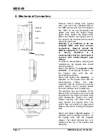
The bypass tube is attached at the side of the vessel with a connecting flange or
a threaded coupling. The installation position is always vertical. The NBK should
only be used for liquids with the medium density specified on the nameplate.
Otherwise the indication may be in error or the float may submerge and give no
level indication. Vessel inner pressure and medium temperature should not
exceed the specified maximum values, as this can lead to instrument damage or
personnel injury. It is imperative to ensure that the level indicator wetted materials
are chemically resistant to the liquid being measured.
Proper operation is also impaired by:
High degree of soiling
•
•
•
•
Solids
Crystallization
Ferrite particles
4.2. Adjustable setpoint switches (option)
The optional adjustable switches serve to signal a preset level.
Important!
Attention !
Observe the maximum electrical ratings for the switches.
Maximum values
Standard
contact
High temperature
contact
Breaking capacity:
40 VA
80 VA
Switching current:
0.8 A
1 A
Switching voltage:
230 V
220 V
4.3. Variable Resistance Transducer
(options..M & W..)
The optional remote electrical sensor converts the liquid level to a resistance
value (Option W). A version of this transducer can also be supplied with an
integral 4-20 mA transmitter (Option M).
Please note max. medium and ambient temperatures.
Page 4
NBK-M_manual_3-5-04.doc


