


Heinrichs Messtechnik
BGN Installation and Operating Instructions
Page 8 of 34
Subject to change without notice
10.1
Mounting requirements
The mounting location must be suitable for a
vertical direction of flow from the bottom to the top.
Important:
If that is impossible, then the flow meter series
BGF
may be installed. This device can be used for both
horizontal and vertical flow directions.
The limit values for temperature and air humidity at the mounting location must be maintained. Avoid corrosive atmospheres. If this
cannot be avoided, ventilation must be installed.
Please ensure that there is adequate clearance from parts that might cause magnetic interferences
such as
solenoid valves and ferromagnetic components like steel brackets/supports.
We recommend the minimum lateral
distance between two adjacently mounted devices to be
300 mm
. The devices can be mounted close together
if vertically offset by one device length. The minimum lateral clearance for interfering steel parts should be
200 mm
.
In case of doubt, check the interference by moving the device back and forth in the selected distance by about
200 mm and evaluate whether the pointer position changes.
Select the mounting location so as to enable a reliable reading of the scale values. Please take note as well of the space
requirement for any possible disassembly of the device.
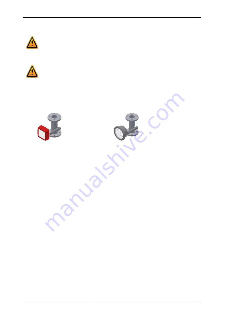
For process temperature < -40 °C and/or > +200 °C the instruments must be equipped with a displaced indication. Please consider
the additional required space. ( see also point 11.1 )
Sample aluminum indicator displaced
Sample st.st. indicator displaced
As a rule, inlet and outlet sections in front of and behind the device are not necessary if the medium does have a linear flow profile.
Avoid mounting accessories converging on one side in front of the device. However, if this is indispensable maintain a minimum
device length of 250 mm as an inlet section.
The nominal size of the pipes to be connected must correspond to that of the meter. Avoid fittings converging on one side directly in
front of the device. As a rule, install valves behind the measuring equipment if there are gases involved.
10.1.1 Mounting / start-up
The device must be mounted in accordance with the direction of flow from the bottom to the top (perpendicularly).
Please observe the prior reference to the BGF-type device.
The nominal size of the device and that of the pipes must be the same. The pressure rating and, hence, the dimensions of the
flanges must coincide. The surface roughness of the flange sealing surface must be suitable for the prescribed gaskets.
Please check whether possible accessories like spring stops, gas/liquid-type dampers are still correctly sitting on the flange. Check
whether the mounting clearance between the flanges of the pipes corresponds to the assembly dimension of the device plus two
gaskets.
To achieve stress-free mounting, the flanges of the pipes must be aligned parallel to each other.
Use connecting bolts and gaskets in the prescribed dimensions. The gaskets must be suitable for the operating pressure, the
temperature and the measured medium. With PTFE-lined devices, use gaskets whose interior and exterior diameter correspond to
the sealing strip of the device.
Tighten the screws crosswise so that the process connections are tight. Refer to the screw torques especially with PTFE-coated
devices.
The maximum torques for PTFE-coated devices are:
DN15/DN25 = 14 Nm/DN50 = 25 Nm/DN80 = 35 Nm/DN100 = 42 Nm (following VDI/VDE Guideline 3513).
Please check whether the pipe is adequately fixed and stable to prevent vibration or swinging of the device. (Do not use steel
mounting parts on the device.)
When used with gaseous medias the installation position of e.g. adjusting valve (e.g. special option). If the device is calibrated to
more than 1.013 bars abs., the valve is usually installed at the flow meter outlet. At 1.013 bars abs. (free outlet) the valve is
installed at the flow meter inlet.
If there is risk of dirt or solid matter penetrating the process pipes, flush them beforehand so that those materials do not get
deposited in the device. Ferromagnetic solid matter such as weld spatters can lead to the breakdown of the device. If these
materials cannot be excluded during normal operating conditions, mount a magnetic filter (accessory) in front of the device. When
using liquids, flush to avoid a surge of gas bubbles. Slowly increase the supply pressure when using gases to prevent pressure
surges. Basically, avoid activation using solenoid valves to prevent the float from shooting upwards.