background image

29 

6.2.5 Communication Parameters 

No. 

Range 

Default 

Description 

Set 

800 

0~99


01 

Comm. Address 

Communication Address. 


801 

802 

0~2


COM1 Baud Rate / COM2 Baud Rate 

0: 9600bps 

1: 19200bp 

2 :115200bps 


803 

804 

0~2


COM1 ParityCheck / COM2 ParityCheck


0: None 

1: Even 

2: Odd 


805 

0~3


COM1 Comm. Mode 

0: Host-slave ASC 


[Modbus ASCII]


1: Continuous ASC 

  [Continuous Sending ASCII] 

2:Cont.[Weight]       

  [Continuous Sending ASCII]


3: USB 


806 

0~2


COM2 Comm. Mode 

0: Host-slave ASC 


[Modbus ASCII]


1: Continuous ASC 

  [Continuous Sending ASCII] 

2:Cont.[Weight]       

  [Continuous Sending ASCII]


807 

1~2 

Print Format 

1

Format 1 

2

Format 2 

See ‘Appendix A. Print Formats’. 


Содержание N59

Страница 1: ...N59 B Wheel Loader Weigher Operation Manual V7 1 KOBASTAR ...

Страница 2: ...ng Declining state Single bucket loading weight Totalized Loading Weight Positive Negative Deviation Value Alarm state Date Time and other auxiliary data are used for judging if Single bucket loading weight is valid and the loading process should be stopped 20 key English keypad with controllable backlight Number and English Alphabet can be inputted The informations of User Name Truck No Goods No ...

Страница 3: ...PAD OPERATION 12 4 2 1 Menu Operation 12 4 2 2 Parameter Setting Operation 12 4 2 3 System Calibration Operation 12 4 2 4 Operation in Loading Process 13 5 INSTALLATION CONNECTION 14 5 1 INSTALLATION 14 5 1 1 Structure of Wheel loader 14 5 1 2 Installation of Weighing Indicator 15 5 1 3 Installation of Position Sensor 16 5 1 4 Installation of Oil Pressure Sensor 17 5 1 5 Cable Laying 18 5 2 TERMIN...

Страница 4: ...ALIBRATION PROCEDURE 31 7 2 EQUIPMENT ADJUSTMENT 32 7 2 1 Wheel loader s Idle Speed Adjustment 32 7 2 2 Position Sensor Adjustment 32 7 2 3 Oil Pressure Sensor Adjustment 34 7 3 SYSTEM CALIBRATION 36 7 3 1 Zero Calibration Zero 36 7 3 2 Zero Compensation Z cmp 38 7 3 3 Span Calibration Cal 40 7 3 4 Span Compensation S cmp 42 7 3 5 Loading Verification 44 8 FAULT TREATMENTS 45 9 WORKING SPECIFICATI...

Страница 5: ...n 5 1 4 Installation of Oil Pressure Sensor Install the oil pressure sensors and plate type three way joints firmly and seal them as prescribed to avoid oil leaking Installation of Position Sensor Install the position sensor according to required position and angle and adjust Detecting Distance to 3 5mm Cable Laying Oil pressure sensor signal cable and position sensor signal cable should be laid i...

Страница 6: ...zed to Totalized Loading Weight automatically and the Deviation Value between Totalized Loading Weight and Setpoint alarm messages will be displayed The operator can judge if the present Single bucket loading weight is valid according to the alarm messages and confirm the loading weight of last bucket according to Negative Deviation Value for avoiding overloading After Totalized Loading Weight rea...

Страница 7: ...lay Refreshing Time Setting Range 0 1 2 0s Keypad 20 key English keypad with controllable backlight Menu Shortcut mode operation with key tone Number and English Alphabet can be inputted Position Sensor Input Interface 2 Switch signal Input Output Voltage DC12V Max Output Current 100mA Oil Pressure Sensor Interface Excitation Voltage Max Current DC12V 100mA DC5V 100mA 2 Oil Pressure signal inputs ...

Страница 8: ...e Humidity Max 85 RH Protection Level IP65 Weight Approx 2 0kg 3 2 Specifications of Position Sensor HALL Type Proximity Switches Operating Voltage DC5 24V Detecting Distance 1 8mm Response Frequency 5KHz Quiescent Current Max 2mA Thread Size M8 1mm Service Temperature 25 70 Protection Level IP67 Standard Detecting Target Permanent magnet Outline Size 30 10 5mm L W T 3 3 Specifications of Oil Pres...

Страница 9: ...8 3 4 System Accuracy Accuracy Grade III Verification Accuracy of Weighing Indicator 0 02 Accuracy of Single Bucket Weight 0 5 1 0 Accuracy of Totalized Loading Weight 1 0 ...

Страница 10: ...d is locked 903 Date Format Hour Minute Second 2 TRUCK Truck No 3 GOODS Goods Name 4 OP Operator Name 5 Bucket Count of Current Shift 6 Totalized Weight of Current Shift 7 Blue It s allowed to lift the lift arm and bucket for weighing Blue It s allowed to put the lift arm down so that the bucket goes down to the lowest position Red Pause State 7 2 L 11 R 12 13 L 5 R 6 1 4 14 9 15 3 10 8 ...

Страница 11: ... Loading Weight Last Bucket Prompt The display area of Totalized Loading Weight will change to red background if Negative Deviation Value 3t it means that the next bucket may be the last one the operator should determine the loading weight of the next bucket according to the actual Negative Deviation Value 14 Single bucket loading weight The display area of Single bucket loading weight will change...

Страница 12: ...is the space between Lower Proximity Switch and Upper Proximity Switch It s divided into Lower Weighing Segment Medium Weighing Segment and Upper Weighing Segment 3 Position Sensor Adjustment Interface A T1 Time spent in Lower Weighing Segment s T2 Time spent in Medium Weighing Segment s T3 Time spent in Upper Weighing Segment s ACC Acceleration Value in Weighing Segments dm s2 4 Position Sensor A...

Страница 13: ...he next option Key Name Description Set Setpoint Parameters Setting 0 9 Number Input A Z English Alphabet Input Print IME Input Method Switch Number English Chinese PinYin Key Name Description Authorization 4 Zero Zero Calibration with unloading and idle speed All Users 7 Z cmp Zero Compensation with unloading and accelerating Administrator 5 Cal Span Calibration with loading and idle speed 8 S cm...

Страница 14: ...gle bucket loading weight is not accurate press the key to deduct it from Totalized Loading Weight Print Print Loading Records 1 Disp Display Interface Switch 2 Lock Key locking Key unlocking 3 Deduct Do Deduct operation if the present Single bucket loading weight is excessive After entering the working state of Deduct the present Single bucket loading weight will be deducted from Totalized Loadin...

Страница 15: ... Port of Lower Oil Chamber Related Operation Terms Arm up Lift the lift arm so that the bucket rises Arm down Put the lift arm down so that the bucket goes down to the lowest position Bucket up Flip the bucket upward to the limit position Bucket down Flip the bucket downward Discharge Flip the bucket downward for discharging materials Shovel Shovel materials into the bucket 2 3 4 1 5 ...

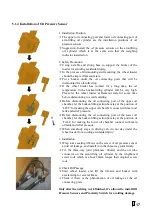
Страница 16: ...Plate 4 Printer Weld the mounting bracket of the weighing indicator firmly on the metal frame of the wheel loader driving cab The installation position should be convenient for operation Suggestion Install the weighing indicator in the driving cab of wheel loader and on the side the door which will not be opened frequently 1 2 3 4 ...

Страница 17: ...m Seat 2 Lift arm 3 Main Mounting Plate 4 Sub mounting Plate 5 Weld nut 6 Thread Pole 7 Nylon Block 8 Fastening Nut for Position Ajustment 9 Magnet Block 10 Upper Proximity Switch 11 Upper Proximity Switch 12 Fastening Nut for Length Ajustment 13 Fastening Nut for Angle Ajustment Sensing Distance Adjustment Adjust the sensing distance between the Magnet Block and the Proximity Switch to 3 5mm Sugg...

Страница 18: ...rt of the upper oil chamber let the bucket lifting action bar stay at the position of LIFT for making the upper oil chamber connect with main oil tank and relief pressure Before dismounting the oil connecting port of the lower oil chamber let the bucket lifting action bar stay at the position of FALL for making the lower oil chamber connect with main oil tank and relief pressure When somebody stay...

Страница 19: ... pipe for protection and fix them with nylon strip Try to keep signal cables away from the place with high temperature and possible extrusion and reserve their bending length enough to avoid being pulled apart 5 2 Terminal 4 5 1 3 2 3 4 1 2 2 1 POWER POSITION LC DN LC UP 5 2 9 2 3 4 3 6 7 8 1 COM1 ON OFF 4 5 1 3 2 ...

Страница 20: ...C Excitation Voltage for Oil Pressure Sensor 4 EXC 5 Excitation Voltage for Oil Pressure Sensor DC5V 5 EXC 12 Excitation Voltage for Oil Pressure Sensor DC12V Note Parameter 105 Signal Range options 0 0 20mV 1 0 5V Parameter 107 Loadcell Channel Selection with Factory Value 2 LC DN UP LC DN Connect the oil pressure sensor installed in the lower oil chamber of arm lifting oil cylinder LC UP Connect...

Страница 21: ...ial communication port No Pin Description 1 VS Output Voltage for Position Sensor DC12V 2 SIN A Position Sensor A Signal Input 3 SIN B Position Sensor B Signal Input 4 VS Output Voltage for Position Sensor COM1 No Pin Description 1 4 Unused 5 GND Ground 6 TXD RS232 Send 7 RXD RS232 Receive 8 9 Unused POSITION 3 4 1 2 5 2 9 2 3 4 3 6 7 8 1 COM1 ...

Страница 22: ...d short circuit fault Find the DC24V terminal with relative stable voltage in the driving cab then connect the terminal 24V of the weighing indicator to the FUSE and connect GND to the metal frame of the driving cab Please make sure that the inputted voltage is correct before power on No Pin Wire Color Description 4 GND Black DC Input 5 24V Red DC Input Note Reverse polarity protection function av...

Страница 23: ...pensation Lift the lift arm and bucket wheel loader with unloading and accelerating for correcting Zero Compensation Coefficient Administrator 3 Span Cal Load Idle Span Calibration Lift the lift arm and bucket wheel loader with loading and idle speed for correcting Span Coefficient 4 Span Comp Load ACC Span Compensation Lift the lift arm and bucket wheel loader with loading and accelerating for co...

Страница 24: ...al Test Factory 2 Simplified Chinese Download Simplified Chinese 3 Complex Chinese Download Complex Chinese 4 Parameter Backup Parameter Backup Administrator 5 Parameter Recovery Parameter Recovery 6 Reset Defaults Reset to factory defaults F6 INF F6 Product Information 1 Version No 1 Version No Factory 2 Serial No 2 Serial No 3 Exfactory Date 3 Exfactory Date 4 ID Code ID Code Supplier 5 Company ...

Страница 25: ... 3 Ton kp Decimal 0 o 1 o o 2 o oo 3 o ooo 103 1 50 10 Display Division kg 1 2 5 10 20 50 If the Weight Variance is less than Display Division value the display value will not change 104 0 200 50 Zero Range kg 105 0 1 0 Signal Range 0 0 20mV 1 0 5V Operating Authorization Administrator 106 0 19 2 Anti Vibration Digital Filter Set Value Cutoff Frequency Set Value Cutoff Frequency 0 None 10 None 1 1...

Страница 26: ...ng Authorization Administrator Note Lower Sensor is the oil pressure sensor installed in the lower oil chamber of arm lifting oil cylinder Upper Sensor is the oil pressure sensor installed in the upper oil chamber of arm lifting oil cylinder 108 0 2 0 Working Mode 0 Truck Mode 1 Mix Mode 2 Axle Type Mode 109 0 1 0 Position Switch Channel Selection 0 Double 1 Single Reset Defaults operation has no ...

Страница 27: ...00 0 10 0 Mag Block Width mm Width of Magnet Block fixed on the Nylon Block of the Position Sensor 205 0 001 9 999 1 000 Run Length Ratio LR Running Length Ratio LR L1 L3 L1 The actual running length of Magnet Block passing by the Lower Proximity Switch Lower Weighing Segment L3 The actual running length of Magnet Block passing by the Upper Proximity Switch Upper Weighing Segment 206 0 0 Unused 20...

Страница 28: ...mpensation Point 5 217 0 0000 99 9999 1 0000 Comp Coeff1 Compensation Coefficient of Point 1 218 Comp Coeff 2 Compensation Coefficient of Point 2 219 Comp Coeff 3 Compensation Coefficient of Point 3 220 Comp Coeff 4 Compensation Coefficient of Point 4 221 Comp Coeff 5 Compensation Coefficient of Point 5 Reset Defaults operation has no effect on the parameter 6 2 3 Setpoint Parameters No Range Defa...

Страница 29: ...ime the alarm message UND T undertime will be displayed 404 0 000 99 999 30 000 Max Weigh Time s If Weighing Time Max Weighing Time the alarm message OV T overtime will be displayed 405 0 1 1 Alarm Sound 0 OFF 1 ON 406 0 1 0 TOT with Alarm Totalizing Permission While Alarming 0 OFF 1 ON 407 0 99999 17000 2 Axle Gross Limit kg 2 Axle Truck Gross Weight Limit 408 0 99999 25000 3 Axle Gross Limit kg ...

Страница 30: ...0 COM1 ParityCheck COM2 ParityCheck 0 None 1 Even 2 Odd 805 0 3 0 COM1 Comm Mode 0 Host slave ASC Modbus ASCII 1 Continuous ASC Continuous Sending ASCII 2 Cont Weight Continuous Sending ASCII 3 USB 806 0 2 0 COM2 Comm Mode 0 Host slave ASC Modbus ASCII 1 Continuous ASC Continuous Sending ASCII 2 Cont Weight Continuous Sending ASCII 807 1 2 1 Print Format 1 Format 1 2 Format 2 See Appendix A Print ...

Страница 31: ...minute and it s not in the processes of F2 Calibration F7 Factory Adj the weighing indicator will lock the keypad and return to Main Display Interface automatically 903 0 2 0 Date Format 0 YYYY MM DD Year Month Day 1 MM DD YYYY Month Day Year 2 DD MM YYYY Day Month Year 904 00 00 23 59 7 59 Shift1 End Time 905 00 00 23 59 15 59 Shift2 End Time 906 00 00 23 59 23 59 Shift3 End Time Reset Defaults o...

Страница 32: ...th unloading and idle speed Actual Loading Process Loading Verification Zero Compensation with unloading and accelerating Span Calibration with loading and idle speed Span Compensation with loading and accelerating Pause or Power off Wheel loader s Idle Speed Adj Oil Pressure Sensor Adjustment Position Sensor Adjustment ...

Страница 33: ...se state with red sign displaying Make sure the bucket of wheel loader is empty BUCKET UP Flip the bucket upward to the limit position ARM DOWN Put the lift arm down so that the bucket goes down to the lowest position Press key Load to display the blue sign Press key Disp to display Position Sensor Adjustment Interface A T1 Time spent in Lower Weighing Segment s T2 Time spent in Medium Weighing Se...

Страница 34: ...he sensing surface of Proximity Switch is good Optional Adjusting Item Adjust manually the parameter 205 Run Length Ratio After lifting the lift arm and bucket with unloading and idle speed if ACC display value is in the range 0 0030 0 0080dm s2 it s not need to modify the set value of Run Length Ratio otherwise try to modify it for ACC display value of the next lifting in the range of empirical v...

Страница 35: ...ed After the Magnet Block passed by the Weighing Segment display NET ADLC UP ADLC DN and ΔAD value If AD2 Value is far greater than AD1 Value then it means that the oil pressure sensors are connected correctly Repeat the above steps for three times if ΔAD Value is stable the adjustment process will be completed NET Single Bucket Loading Weight without Acceleration Compensation LC UP Oil Pressure S...

Страница 36: ... Check if the actual operation process is correct Check if the oil pressure sensors are connected correctly Refer to 5 3 1 Oil Pressure Sensor Connector Parameter 107 Loadcell Channel Selection and 105 Signal Range ΔAD Value Unstable The variation of AD Value has exceeded 100 Do Wheel loader s Idle Speed Adjustment again ...

Страница 37: ...UCKET UP Flip the bucket upward to the limit position ARM DOWN Put the lift arm down so that the bucket goes down to the lowest position Press key Load to display the blue sign Press key Zero to display interface Zero Calibration Lift the lift arm and bucket with idle speed After the Magnet Block passed by the Weighing Segment display Blue sign New Zero Value New Run Length Ratio New IdleAcc Value...

Страница 38: ...of Zero Value and IdleAcc Value A0 are in the allowable range Zero Calibration process will be completed Press key Pause to enter Pause state with red sign displaying Alarm Fault Description Sulution Zero Limit Zero Value is not in the allowed range 0 130000 Do Oil Pressure Sensor Adjustment again LR Limit Run Length Ratio is not in the allowed range 0 001 9 999 Do Position Sensor Adjustment again...

Страница 39: ...nsation Lift the lift arm and bucket with the accelerator at the actual loading operation state and do the best to keep the accelerator stable After the Magnet Block passed by the Weighing Segment display Blue sign New Zero Compensation Coefficient Compensation Difference C ER New Zero Compensation Coefficient Old Zero Compensation Coefficient AD AD Value at Weighing Segment ACC Acceleration Value...

Страница 40: ...ange Zero Compensation process will be completed Press key Pause to enter Pause state with red sign displaying Alarm Description Sulution Too Small Signal AD Value Zero Value 99 Do Wheel loader s Idle Speed Adjustment again Z CMP Limit Zero Compensation Coefficient is not in the allowed range 0 0000 99 9999 Do Oil Pressure Sensor Adjustment again ...

Страница 41: ...are Weight BUCKET UP Flip the bucket upward to the limit position ARM DOWN Put the lift arm down so that the bucket goes down to the lowest position Press key Load to display the blue sign Press key Cal to display interface Span Calibration Lift the lift arm and bucket with idle speed After the Magnet Block passed by the Weighing Segment display Blue sign Weighing Result Message Ent Input Cal Weig...

Страница 42: ...xit without saving Repeat the above steps for three times if the variation of Span Coefficient is in the allowable range Span Calibration process will be completed Press key Pause to enter Pause state with red sign displaying Alarm Description Sulution Too Small Signal AD Value Zero Value 110 Check if there are enough materials loaded in the wheel loader s bucket Do Oil Pressure Sensor Adjustment ...

Страница 43: ...ompensation Lift the lift arm and bucket with the accelerator at the actual loading operation state and do the best to keep the accelerator stable After the Magnet Block passed by the Weighing Segment display Blue sign Weighing Result Message Ent Input Cal Weight Press key Ent to display the interface Input Calibrating Weight After inputting the value of Calibrating Weight press key Ent to display...

Страница 44: ...tion process will be completed Press key Pause to enter Pause state with red sign displaying Alarm Description Sulution Too Small Signal Weighing Result Calibrating Weight 99 Check if the actual weight of the materials in the wheel loader s bucket is consistent with the inputed Calibrating Weight Do Oil Pressure Sensor Adjustment again Do Wheel loader s Idle Speed Adjustment again S CMP Limit Span...

Страница 45: ... to keep the accelerator stable After the Magnet Block passed by the Weighing Segment display blue sign and record weighing result Repeat the above steps if the weighing errors are in the allowable range the preliminary Loading Verification process is completed Do Loading Verification with empty bucket 1 2 bucket materials and a full bucket of materials and use truck scale for checking weighing er...

Страница 46: ...nce between the proximity switch and the magnet block is beyond the detecting range of 1 8mm Check the relevant parameter value are correct Check if the proximity switch is damaged Oil Pressure Sensor Faults Check if the signal connection of oil pressure sensor is correct Check if there is the phenomenon of oil leakage at the oil connecting ports Check the relevant parameter value are correct Chec...

Страница 47: ... red sign displaying and then let the bucket go down to the lowest position Set Setpoint Parameters Press key Load to enter loading state with the blue sign displaying After shoveling materials into the bucket flip the bucket upward to the limit position After the wheel loader reached the loading position with relatively flat ground lift the lift arm and bucket with accelerating for weighing Once ...

Страница 48: ...eAcc Value Acceleration Value at Idle Speed After doing Zero Calibration keep the bucket at the limit position and put the lift arm down so that the bucket goes down to the lowest position Lift the lift arm and bucket with the accelerator at the actual loading operation state and do the best to keep the accelerator stable If the display weight exceeds 30kg then it s need to do System Calibration a...

Страница 49: ...NO ADD it means that the present Single bucket loading weight has not been added to Totalized Loading Weight and it s not allowed to discharge materials from the bucket It s need to lift the lift arm for weighing again After weighing finished flip the bucket downward for discharging materials After the bucket going down to the lowest position the weighing indicator will display the blue sign again...

Страница 50: ...0 00t 59 90t 12 LOADING RECORD NO DATE TIME OP GOODS TRUCK SET TOT PCS 23 25 01 23 59 12 200 05 20 2009 23 59 45 01 00 00000010 60 00t 59 90t 12 4 80t 2 60 LOADING RECORD Weighing Normal S Stall Alarm L Lower Limit Alarm of Single bucket loading weight H Upper Limit Alarm of Single bucket loading weight D Undertime Alarm V Overtime Alarm ...

Страница 51: ...2 1 Undertime Alarm 40009 3 1 Overtime Alarm 40009 4 1 Upper Limit Alarm of Single bucket loading weight 40009 5 1 Lower Limit Alarm of Single bucket loading weight 40009 6 40009 7 40009 8 40009 9 40009 10 40009 11 40009 12 40009 13 40009 14 40009 15 40009 31 Real time Weight Value Long 40011 R 03 Display Unit of Loading Weight Short 40013 R 03 Display Unit of Totalized Loading Weight Short 40014 ...

Страница 52: ...rt 40021 40032 R 03 Char 1 8 1 Second 2 Minute 3 Hour 4 Day 5 Month 6 Week 7 Year 8 14H 20D Char 9 12 Totalized Loading Weight Long Char 13 14 Bucket Count Short Char 15 24 Goods ASCII Note Char1 2DH means No Record Record Query Write the Record No for query into the register 40019 at first then read the whole data packet of the registers 40021 40032 ...

Страница 53: ...bastar Elektronik San Tic Ltd Şti Elit San Sit Fevzi Çakmak Mah Ayyıldız Cad No 103 A Karatay Konya TURKEY Tel 90332 249 3815 Website www kobastar com E mail bilgi at kobastar com CPC16 042376 2014F108 43 ...

Отзывы:

Похожие инструкции для N59