ASSEMBLY INSTRUCTIONS
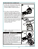
5. Rotate the inertia nut (D) and get the gear to
face the bearing seat (C). Then the bearing
seat (C) is locked and stable (See Figures 4)
6. To properly mount the sanding pad (B) to the
the bearing seat (C), remove the plastic
cap protecting the threads on the sanding
pad (B). Align the threads of sanding pad (B)
onto the bearing seat (C) and turn the pad
clockwise by hand. Make sure that the
sanding pad (B) is fixed tightly (See Figure 5).
11
7. Mount sanding paper (not provided) onto the
sanding pad (B).
4
Unlocked
WARNING
Only use sanding paper which has an RPM rating
equal or greater than 10,000 RPM.
Before using tool, always make sure attachments
are properly mounted/secured. If attachments are
not properly mounted/secured, they can present
a serious hazard and may cause bodily injury for
the operator or anyone in or around the work area.
Always follow the attachment manufacturer’s
specifications for properly attaching accessories
to tool.
5
plastic cap
Locked
6
Unlocked
After mounting of sanding pad (B), rotate the
inertia nut (D) 90°to unlocked position
(See Figure 6).


