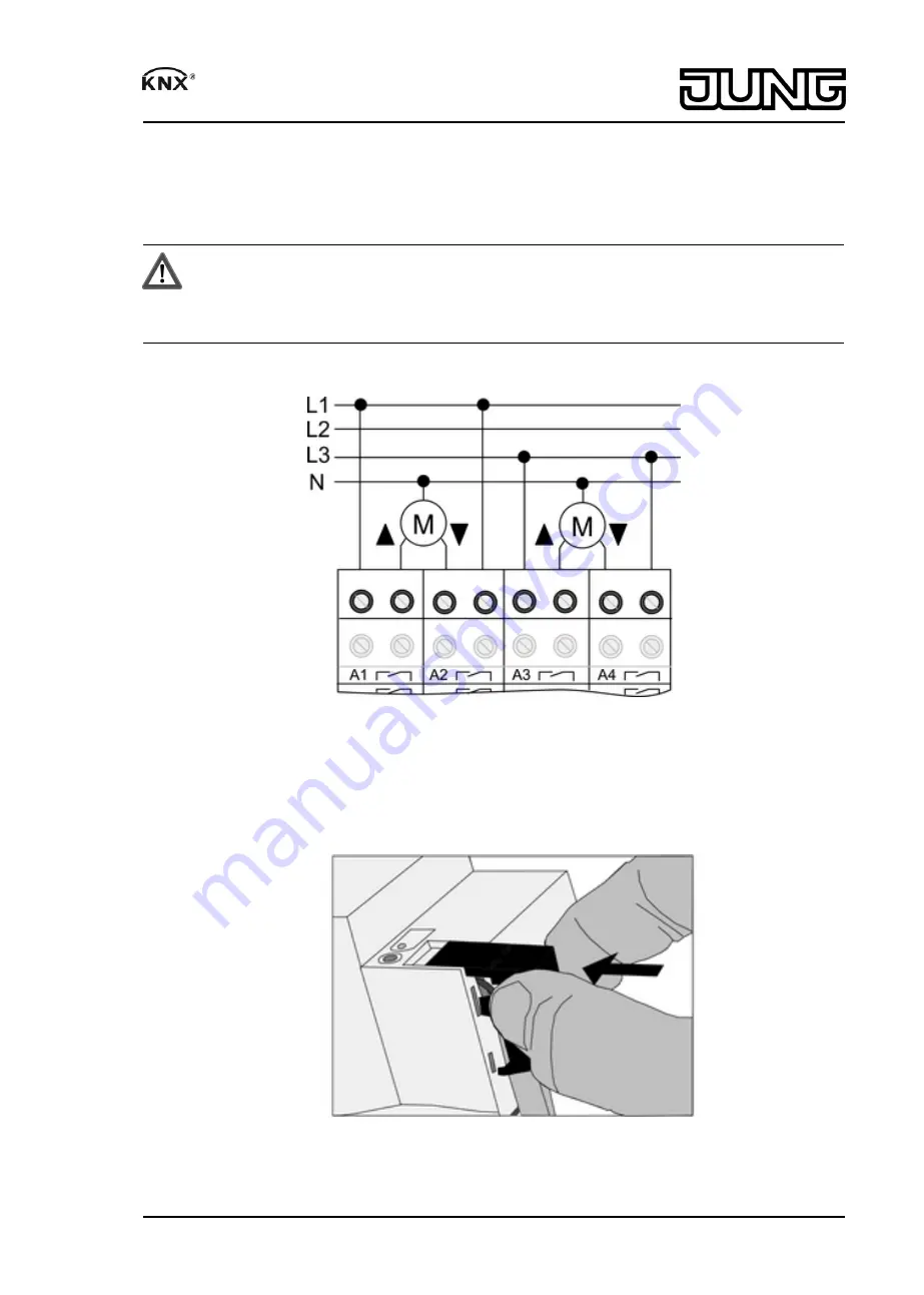
Connecting blind/shutter drives
For blind/shutter drives, each pair of adjacent relay outputs forms a blind/shutter output. In each
case the left-hand relay output
A1, A3...
is intended for the up direction, and the right-hand load
output
A2, A4...
for the down direction.
Output is parameterised as a blind/shutter output.
CAUTION!
Overloading the device leads to excessive heating.
Damage to the device and the connected cables may result.
Do not exceed the maximum current carrying capacity.
o
Connect drives (figure 5).
Figure 5
Installing the cover
It is necessary to install a cover to protect the bus connection against hazardous voltages in the
connection area.
Figure 6: Installing the cover
o
Route the bus line towards the rear.
7/11
82560023
J:0082560023
05.08.2013
Switch actuator / blinds actuator


