


KNOX VIDEO
RS8x8HB ROUTING SWITCHER
KNOX VIDEO
RS8x8HB ROUTING SWITCHER
Page 12
Page 11
3.4.5 STORING AND RECALLING CROSSPOINT PATTERNS
To STORE the currently loaded crosspoint pattern to one of the eight pattern
storage areas, send the three-byte command:
Sn (ENTER),
where n is a number from 1 to 8. The pattern stored in that memory area will be
overwritten with the current pattern.
To RECALL and load one of the eight crosspoint patterns in the battery back
up memory, send the three-byte command:
Rn (ENTER),
where n is a number from 1 to 8.
3.4.6 TIMED SEQUENCER
The RS8x8HB can be set to cycle continuously through its eight stored patterns
on a timed basis. To set the time interval and start the cycling send the four-byte
command:
Tnnn (ENTER),
where nnn is a one- to three-digit number from 1 to 999.
To stop the cycling, send the two-byte command:
N (ENTER).
3.4.7 LAMP TEST
The lamp test which occurs automatically on power-up can be initiated through
the RS232 port by sending the two-byte command:
T(ENTER)
The lamp test does not disturb the existing crosspoint pattern.
3.5 ANSWERBACK MODES
The user may choose between two modes of answerback: verbose and non-
verbose. Select the mode using position 3 of the programming switch located on
the rear panel of the RS8x8HB. Position 3 ON is verbose, while position 3 OFF is
non-verbose.
In the verbose mode, each time a routing command is sent, the current routing
map will be reported on the RS232 line followed by the word DONE.
The switches are read by the microprocessor only at power-up; for switch
configuration changes to take effect, cycle the power input to the RS8x8HB.
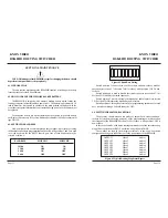
3.6 READING SYSTEM STATUS
The crosspoint status can be read from the RS232 port at any time by sending
the two-byte command:
D(ENTER)
A condensed version of the status can be read by sending:
D0(ENTER)
The status report does not disturb the existing crosspoint pattern.
OUTPUT 1
Video 3
Audio 1
OUTPUT 2
Video 2
Audio 2
OUTPUT 3
Video 1
Audio 3
OUTPUT 4
Video 6
Audio 6
OUTPUT 5
Video 7
Audio 7
OUTPUT 6
Video 8
Audio 8
OUTPUT 7
Video 5
Audio 1
OUTPUT 8
Video 4
Audio 1
In the non-verbose mode only the word DONE will be reported.
In either mode, an incorrect or meaningless command will cause the word
ERROR to be reported.
Figure 3.1 Typical Routing Map Status Report


