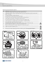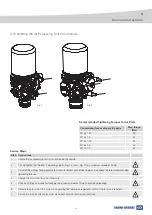
11
3
Service Instructions
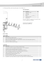
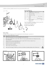
3 2 Removal and Replacement of the Heater Assembly (B)
Service Steps
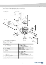
Part Identification
Item
Description
Qty
1
Heater assembly
1
2
Screw
1
1
2
M27x1 (12V & 24V)
Bayonet - ISO15170
For Service Kit Part Number see
www.knorr-bremseCVS.com
Note that component numbering may not correspond to that
shown on separate Service Kit leaflets.
Step Service task
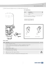
Removal of the heater assembly
1
Clean the outside of the air processing unit and the surroundings of the heater area.
2
Unscrew electrical connector locking ring and unplug connector (not shown).
3
Undo screw (2).
4
Remove heater assembly (1).
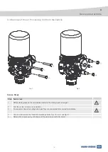
Replacement of the heater assembly
1
Fit new heater assembly (1) into body.
2
Tighten new screw (2) to a torque of 3.5 Nm.
3
Refit the electrical connector and hand tighten the locking ring (not shown).


