


Diaphragm liquid pump NF 25, NFB 25
Technical data
KNF Flodos AG BA_NF25_NFB25_EN_07_159615
Translated from the Original Operating and Installation Instructions
6
4. Technical data
Pump materials
The pump type
KP
stands for:
Assembly
Material
1)
Pump head*
PP
Valve plate / seals
EPDM
Diaphragm
EPDM
Resonating diaphragm
EPDM
Tab. 2
1)
according to DIN ISO 1629 and 1043.1
The pump type
KT
stands for:
Assembly
Material
1)
Pump head*
PP
Valve plate / seals
FFKM
Diaphragm
PTFE-coated
Resonating diaphragm
FFKM
Tab. 3
1)
according to DIN ISO 1629 and 1043.1
The pump type
TT
stands for:
Assembly
Material
1)
Pump head*
PVDF
Valve plate / seals
FFKM
Diaphragm
PTFE-coated
Resonating diaphragm
FFKM
Tab. 4
1)
according to DIN ISO 1629 and 1043.1
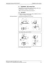
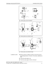
* The pump head (Fig. 1) comprises a connecting plate and an intermedi-
ate plate.
Hydraulic ratings
Parameter
Value
Flow rate NF 25 DC-M and DCB [ml/min]
1), 2)
250
Flow rate NF 25 DCB-4 [ml/min]
1), 2)
25-250
Flow rate NFB 25 DCB-4B [ml/min]
1), 2)
2x 50-300
Flow rate NFB 25 DCB-B [ml/min]
1), 2)
2x 300
Permissible pressure [bar g]
1
Suction head [mWG]
3
Tab. 5
1)
Measured with water and using KNF standardised test equipement at
atmospheric pressure, KP pump head material
2)
Flow rates may vary from the values shown, depending on fluid viscosi-
ty, ambient temperature, pump head material and the hoses / hose con-
nectors used.
Hydraulic connections
Parameter
Value
Recommended hose size ID [mm]
4
Tab. 6


