KNF NF 25 DC-M Скачать руководство пользователя страница 23

Diaphragm liquid pump NF 25, NFB 25 

Troubleshooting 

KNF Flodos AG BA_NF25_NFB25_EN_07_159615 
Translated from the Original Operating and Installation Instructions


23 

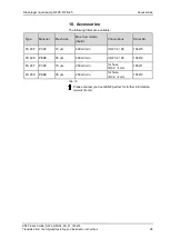
Flow rate, suction head or pressure head is too low 

The pump does not achieve the performance stated in the technical data or on the data sheet. 

Possible cause 

Remedy 

Components in the system 
connected to the suction and 
pressure sides, such as hoses, 
valves or filters, are causing too 
much resistance 

  Modify installation, check the cross-sections of components 

Hose connections are not leak-
tight 

  Secure transition joints between hose and hose connections 

with clamps or clamping elements 

Particles in the pump 

  Clean the pump head, install suction-side filter if required 

(see Chapter 8.2) 

Viscosity of the transferred 
medium is too high 

  Contact KNF 

Incorrect interchange of pres-
sure and suction line connec-
tions 

  Remove pressure and suction lines and reconnect correctly 

The pump parts are not re-
sistant to the medium to be 
transferred 

  Replace the pump head with a compatible version 

Tab. 10 


Fault cannot be rectified 

If you are unable to identify any of the above causes, please send 
the pump to KNF customer service (see address on last page). 

  Flush the pump to clear the pump head of any hazardous or 

aggressive liquids (see Chapter 8.2.1). 

  Dismantle the pump. 

  Clean the pump (see Chapter 8.2.2). 

  Send the pump, with completed decontamination declaration 

(see Chapter 10), to KNF customer service stating the nature 
of the transferred medium. 

Содержание NF 25 DC-M

Страница 1: ...ry specific designation with no technical relevance Contents Page 1 About this document 2 2 Use 3 3 Safety 4 4 Technical data 6 5 Assembly and function 9 6 Installation and connection 10 7 Operation 1...

Страница 2: ...mbol indicates a potential danger It also indicates the possible consequences of failure to observe the warning The signal word e g Warn ing indicates the level of danger Here you will see actions for...

Страница 3: ...a medium check the compatibility of the materials of the pump head pump housing diaphragm and valves with the medium The temperature of the medium must lie within the permissible temperature range see...

Страница 4: ...onnel have read and understood the Oper ating and Installation Instructions and in particular the Safety chapter Always ensure adherence to all pertinent accident prevention and safety regulations whe...

Страница 5: ...d machinery may not be commissioned until such time as it has been determined that the machine in which the partly completed machinery is to be assem bled conforms to the provisions of the Machinery D...

Страница 6: ...ead PVDF Valve plate seals FFKM Diaphragm PTFE coated Resonating diaphragm FFKM Tab 4 1 according to DIN ISO 1629 and 1043 1 The pump head Fig 1 comprises a connecting plate and an intermedi ate plate...

Страница 7: ...1 g 64 Tab 7 Specifications NF 25 DCB DCB 4 Motor option DCB 4 DCB 12V DCB 24V Supply voltage V 10 26 4 12 24 Power consump tion W 2 9 2 8 2 9 I load max A 0 11 0 25 0 23 0 12 Lead size AWG28 Protecti...

Страница 8: ...on class IP50 Weight 1 g 210 Tab 9 In the case of type NFB25 DCB 4B the supply voltage is not designed for operation with pulse width modulated voltages PWM However a PWM signal frequency 1 20kHz can...

Страница 9: ...2 Pump assembly The diaphragm liquid pumps are based on reciprocating displace ment pump technology The elastic diaphragm 4 is moved up and down by the eccentric 5 and the connecting rod 6 In the down...

Страница 10: ...ion Only install the pump under the operating parameters and condi tions described in Chapter 4 Technical data Observe the safety precautions see Chapter 3 6 1 Installation Before installation store t...

Страница 11: ...structions 11 Fig 6 Mounting dimensions NF 25 DCB 4 Fig 6 Mounting dimensions NFB 25 DCB B Fig 8 Mounting dimensions NFB 25 DCB 4B Make sure that the installation location is dry and the pump is prote...

Страница 12: ...m the Original Operating and Installation Instructions 12 Generally speaking the pump can be installed in any position For maximum accuracy and rapid venting of one headed pumps please install as show...

Страница 13: ...motor cable 6 3 Hydraulic connection Only connect components to the pump that are designed to handle the hydraulic data of the pump see Chapter 4 Technical data Only use hoses that are suitable for t...

Страница 14: ...lsation pressure surges in NFB pumps Configure pump head hoses in parallel see Fig 8 Keep hoses between pump and junction as short as possible Cause as little narrowing as possible with connection ele...

Страница 15: ...ct with the pump drive Avoid contact with flammable materials Excessive pressure and the inherent dangers thereof can be prevented by placing a bypass line with a pressure relief valve between the pre...

Страница 16: ...ation www knf com Switching on the pump In order to ensure that the pump starts every time make sure that counterpressure is reduced to an acceptable level before start up This should also be done dur...

Страница 17: ...pump NF 25 DCB and NF 25 DCB 4 Fig 15 Flow rate of pump NF 25 DCB 4 depending on control voltage 0 00 0 05 0 10 0 15 0 20 0 25 0 30 4 0 2 0 0 0 2 0 4 0 6 0 8 0 10 0 Suction height mWg Pressure mWg Fl...

Страница 18: ...F25_NFB25_EN_07_159615 Translated from the Original Operating and Installation Instructions 18 Flow rate NFB 25 Fig 16 Flow rate of pump NFB 25 DCB B and NFB 25 DCB 4B per pump head Fig 17 Flow rate o...

Страница 19: ...caustic burns or poisoning are possible Wear protective clothing if necessary e g pro tective gloves Flush the pump with a neutral liquid and pump empty With NFB pumps make sure that both pump heads a...

Страница 20: ...air 8 2 5 Assembling the pump head Screw diaphragm 8 with washer 9 into connecting rod Make sure that no washers 9 fall into the pump housing Use the head plate 2 to carefully tighten the diaphragm In...

Страница 21: ...Original Operating and Installation Instructions 21 CAUTION Escaping liquid After assembly the pump may not be leak tight due to incorrect assembly damaged or soiled seal faces or other reasons Run pu...

Страница 22: ...al valves and filters Diaphragm anchor valves or seals are worn Replace diaphragm anchor valves and seals see Chapter 8 3 Tab 13 Pump is not priming Possible cause Remedy Suction side of pump not con...

Страница 23: ...ents Particles in the pump Clean the pump head install suction side filter if required see Chapter 8 2 Viscosity of the transferred medium is too high Contact KNF Incorrect interchange of pres sure an...

Страница 24: ...wing filters are available Type Material Mesh size Max flow volume liquid Connections Order No FS 60 T PVDF 70 m 600 ml min UNF 1 4 28 165210 FS 60 X PEEK 35 m 600 ml min UNF 1 4 28 165212 FS 25 T PVD...

Страница 25: ...n condition that the customer provides certification of the transferred media and the cleaning of the pump decontamination declaration In order to send a product back use the decontamination declarati...

Страница 26: ...Diaphragm liquid pump NF 25 NFB 25 For your notes KNF Flodos AG BA_NF25_NFB25_EN_07_159615 Translated from the Original Operating and Installation Instructions 26...

Страница 27: ...KNF worldwide Please find your local KNF partners at www knf com...

Отзывы: