


Troubleshooting
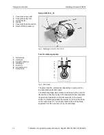
Diaphragm Pumps N 035.18
20
Translation of original Operating Instructions, English, KNF 121228-121398 04/14
9. Troubleshooting
DANGER
Extreme danger from electrical shock!
Disconnect the pump power supply before working
on the pump.
Make sure the pump is de-energized and secure.
Check the pump (see Tab. 13 to 16).
Pump does not transfer
Cause
Fault remedy
No voltage in the power source
Check room fuse and switch on if necessary.
Thermal switch has operated
following to over-heating.
Disconnect pump from mains.
Allow pump to cool.
Trace cause of over-heating and eliminate it.
Connections or lines blocked.
Check connections and lines.
Remove blockage.
External valve is closed or filter
is clogged.
Check external valves and filters.
Condensate has collected in
pump head.
Detach the condensate source from the pump.
Flush pump (see Section 8.2.1).
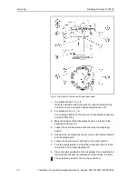
Diaphragm or reed valves
(valve plate) are worn.
Replace diaphragm and reed valves (valve plate), (see
Section 8.3).
Tab. 13
Flow rate, pressure or vacuum too low
The pump does not achieve the output specified in the Technical data or the data sheet.
Cause
Fault remedy
Condensate has collected in
pump head.
Detach the condensate source from the pump.
Flush pump (see Section 8.2.1).
There is gauge pressure on
pressure side and at the same
time vacuum or a pressure
above atmospheric pressure on
suction side.
Change the pressure conditions.
Pneumatic lines or connection
parts have an insufficient cross
section.
Disconnect pump from system to determine output values.
Eliminate throttling (e.g. valve) if necessary.
Use lines or connection parts with larger cross section if
necessary.
Leaks occur on connections,
lines or pump head.
Check that tubes sit correctly on hose nozzles.
Replace leaky tubes.
Eliminate leaks.
Connections or lines completely
or partially jammed.
Check connections and lines.
Remove the jamming parts and particles.
Head parts are soiled.
Clean head components.
Diaphragm or reed valves
(valve plate) are worn.
Replace diaphragm and reed valves (valve plate),
(see Section 8.3).