


Servicing
Diaphragm Pumps N 035.18
18
Translation of original Operating Instructions, English, KNF 121228-121398 04/14
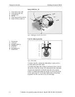
Fig. 6: Pump parts for versions with aluminium head
1. For pumps N 035.1.2 A_.18:
On both pneumatic head connections, open the head connec-
tion union nut on one pump head and pull the hose off.
2. For pumps N 035.3 A_.18:
At one pump head open the union nut of pneumatic connection
and pull off the tube.
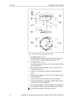
3. Mark the position of the diaphragm head C in relation of the
housing A with a pencil.
4. Loosen the four allen screws B and remove the diaphragm
head C.
5. Unscrew the countersunk screw D, remove the retainer plate E
and the diaphragm F.
6. Loosen the four screws G and remove the cover plate H.
7. Turn the counterweight J so that the connection rod K is in the
mid-position; fit the new diaphragm F.
8. Place the retainer plate E on the diaphragm F and carefully but
formly tighten the new countersunk screw D (torque: 5.0 Nm).
The self-locking screw D can only be used once.