background image

Page 9 of 13 


Maintenance 

1.  Before dismantling the unit, exhaust the air in the line completely. 

2.  Dismantle the components and clean them in kerosene and blow with compressed air. 

3.  Check for damages in the O-rings (15), (16.1), (17) and at sealing areas in the valve cone 

rubber, spherical relieving seating, seating area of the housing, etc. Replace if needed or 
clean and reassemble. 

4.  For assembly of the unit: Apply general purpose grease on the O-rings (15), (16.1), (17) and 

on the cylindrical surface of the valve cone (13), on threads of the adjusting screw (7), and on 
bearing washer (6). Reassemble all the components. 
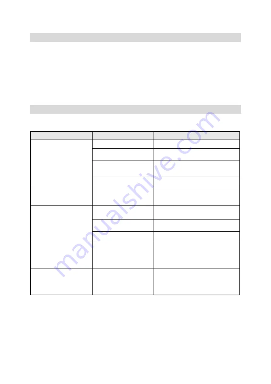
Troubleshooting 

Use the table below to troubleshoot problems before contacting service personnel or your local 
dealer. If the problem continues after troubleshooting, call your local dealer for assistance. 

Failure 

Possible Cause 

Corrective Action 

Continuous leak through the 
knob (1). 


Diaphragm (9) damaged.


Replace Diaphragm assembly (9).


Relieving spherical seating 
of the valve cone damaged. 

Replace valve cone assembly (13).


Dirt found in between the 
seating and the valve cone 
(13). 

Clean and reassemble.


O-ring (16.1) damaged.


Replace the o-ring (16.1).


Air leaks through housing 

and bottom plug (16) 
interface. 

O-ring (15) damaged. 

 
Replace the o-ring (15).


Setting pressure goes on 

increasing slowly. 

Relieving spherical seat of 

the valve cone damaged. 

Replace the valve cone assembly (13).


Dirt found in between the 
seating and the valve cone. 

Clean and reassemble.


O-ring (16.1) damaged.


Replace the o-ring (16.1).


After frequent use of 

adjustment knob, the 
pressure setting 
becomes  

       impossible.


Wearing out of the adjusting   
Screw (7).


Replace the adjusting screw assembly 
and apply general purpose grease on 
threads and at washer (6).


Supply pressure directly 

connected to outlet 
port and making 
pressure setting 
impossible.


Valve cone assembly (13) 
is stuck.


Dismantle the valve assembly (13). 
Clean using kerosene and air jet. 
Reassemble after applying general 
purpose grease on o-ring (17) and on 
the valve cone cylindrical portion.


Содержание 57392

Страница 1: ...ner s Manual WARNING Read carefully and understand all ASSEMBLY AND OPERATION INSTRUCTIONS before operating Failure to follow the safety rules and other basic safety precautions may result in serious...

Страница 2: ...that you read the entire manual to become familiar with this product before you begin using it This air regulator is designed for certain applications only Northern Tool Equipment is not responsible...

Страница 3: ...ations 4 Important Safety Information 4 Specific Operation Warnings 6 Main Parts of Product 7 Assembly Instructions 8 Before Each Use 8 Operating Instructions 8 Maintenance 9 Troubleshooting 9 Parts D...

Страница 4: ...AR 3 58 PSI 0 2 4 BAR 8 100 PSI 0 5 7 BAR Technical Specifications Part Port Size Flow Rate Max Pressure Gauge Port Size Height Width CFM LPM Inch mm In mm 57392 140 4000 1 8 6 5 165 2 75 70 Important...

Страница 5: ...ng the tool Do not use the tool while you are tired or under the influence of drugs alcohol or medication A moment of inattention while operating the tool may result in serious personal injury Dress p...

Страница 6: ...e re use Use only accessories that are recommended by the manufacturer for use with your product Accessories that may be suitable for one product may create a risk of injury when used with another too...

Страница 7: ...ad Screw 4 5 Bonnet 1 6 Bearing Washer 1 7 Adjusting Screw Assembly 1 8 Main Spring 1 9 Diaphragm Assembly 1 10 Venturi Tube 1 11 Housing 1 12 Port Plug Assembly 2 12 1 Port Plug 2 12 2 O Ring 2 13 Va...

Страница 8: ...ction of air flow towards tool equipment WHERE TO INSTALL A PRESSURE GAUGE Pressure gauges must be installed on the pressure gauge port on the Regulator Regulator has 1 8 pressure gauge port The Press...

Страница 9: ...damaged Replace Diaphragm assembly 9 Relieving spherical seating of the valve cone damaged Replace valve cone assembly 13 Dirt found in between the seating and the valve cone 13 Clean and reassemble O...

Страница 10: ...Page 10 of 13 Parts Diagram...

Страница 11: ...16 Bottom Plug 1 16 1 O Ring 1 17 O Ring 1 18 Circlip 1 Replacement Parts For replacement parts and technical questions please call Customer Service at 1 800 222 5381 Not all product components are av...

Страница 12: ...laim contact Us at 1 800 222 5381 identify the product by make and model number and follow the claim instructions that will be provided The product and the purchase receipt must be provided to Us in o...

Страница 13: ...Page 13 of 13 Distributed by Northern Tool Equipment Company Inc Burnsville Minnesota 55306 www northerntool com Made in India...

Отзывы: