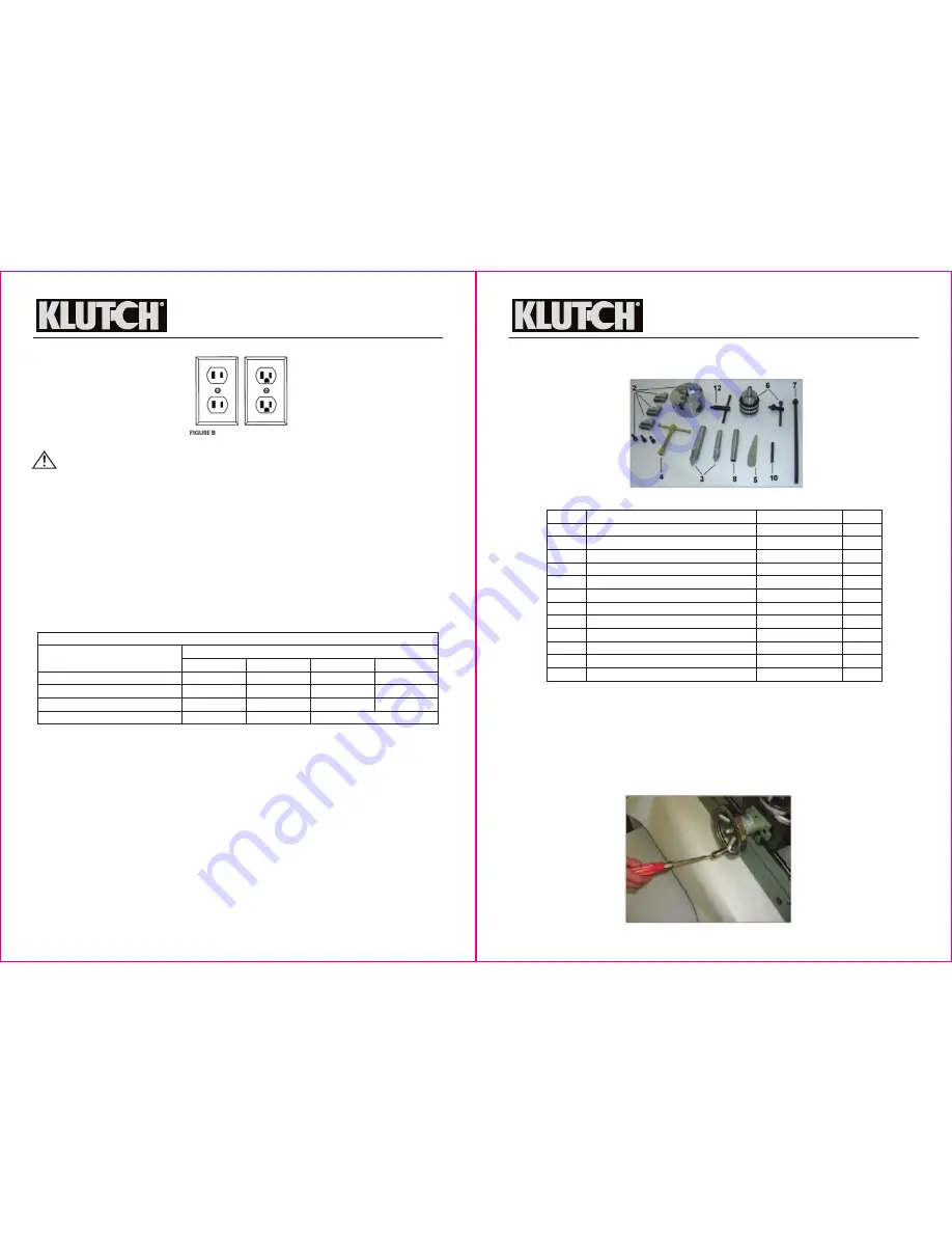
150'
14 AWG
12 AWG
12 AWG
Nameplate AMPS
25'
18 AWG
18 AWG
16 AWG
14 AWG
50'
16 AWG
16 AWG
16 AWG
12 AWG
100'
16 AWG
14 AWG
14 AWG
Minimum Wire Size Of Extension Cords
0-6
6-10
10-12
12-16
Cord Length
NOT RECOMMENDED
6 of 34
7 of 34
Milling and Drilling Machine
OWNER’S MANUAL
Extension Cords
WARNING:
• USE A PROPER EXTENSION CORD. Make sure your extension cord is in good condition.
When using an extension cord, be sure to use one heavy enough to carry the current your
product will draw. An undersized cord will cause a drop in line voltage, resulting in loss of
power and cause overheating.
• Be sure your extension cord is properly wired and in good condition. Always replace a
damaged extension cord or have it repaired by a qualified person before using it. Protect
your extension cords from sharp objects, excessive heat and damp or wet areas.
• Grounded tools require a 3-wire extension cord. Double Insulated tools can use either a 2- or
3-wire extension cord.
• As the distance from the supply outlet increases, you must use a heavier gauge extension
cord. Using extension cords with inadequately sized wire causes a serious drop in voltage,
resulting in loss of power and possible tool damage.
• The smaller the gauge number of the wire, the greater the capacity of the cord. For example,
a 14-gauge cord can carry a higher current than a 16-gauge cord. Minimum extension cord
wire size is shown in the following table:
• When using more than one extension cord to make up the total length, make sure each cord
contains at least the minimum wire size required.
• If you are using one extension cord for more than one tool, add the nameplate amperes and
use the sum to determine the required minimum cord size.
• If you are using an extension cord outdoors, make sure it is marked with the suffix W-A (W in
Canada) to indicate it is acceptable for outdoor use.
• Make sure your extension cord is properly wired and in good electrical condition. Always
replace a damaged extension cord or have it repaired by a qualified electrician before using
it.
• Protect your extension cords from sharp objects, excessive heat, and damp or wet areas.
Unpacking Instructions
This machine has been inspected and tested before delivery. Once it is properly installed it can
be operated immediately. The machine is covered with water-proof and oil-resisting cloth, fixed
tightly on a pallet and packed in wooden crate. In the crate, there is also a box of accessories.
The steel fastening straps around the crate are under tension. Cut off the straps with shears.
When removing the straps, the workers should wear eye-protecting glasses and gloves. Please
take care since the sheared edges are very sharp. After taking off the straps, remove the nails
and unpack the wooden crate.
Milling and Drilling Machine
OWNER’S MANUAL
Open the box of accessories and check the accessories according to the photo shown below
(Fig.1). Check them with the Packing List.
When installing the machine, the user should provide a solid pedestal to support the machine.
The pedestal should be level and well adjusted. The installation location should allow enough
area for operating. On the left of the machine, there should be enough area for turning rod
material.
On the surface of the machine, there is a protective layer of oil which can be cleaned with
noncorrosive kerosene or petroleum solvent. After installation and cleaning, the machine should
be lubricated (see Operating Instruction/Lubrication).
For shipping reasons, the feeding handle of the Transverse Wheel (9) was installed inwards.
Before operation, it should be reinstalled outwards as shown in Fig. 2.
No.
1
2
3
4
5
6
7
8
9
10
11
12
Description
Milling/Drilling Machine
Spindle chuck, jaws (3), set screws (3)
Dead Centers
Pressing Cutter Wrench
Wedge
Drilling Chuck & Key
Draw Bar
Drill Taper Shank
Flange (on machine)
Locking Lever
Owner’s Manual (this manual)
Chuck Key
Specification
L-H007
Ø100
Morse No. 2 & 3
JS16
MT #2
Qty.
1
1
1 each
1
1
1
1
1
1
1
1
1
Fig. 1: Accessories
Fig. 2


