

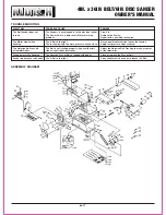


4IN. x 36IN. BELT/6IN. DISC SANDER
OWNER’S MANUAL
4 of 7
• Whenever adjusting or replacing any parts on the tool, turn
switch OFF and remove the plug from power source.
• Recheck table handle and bolts. They must be tightened
securely.
• Make sure all guards are properly attached. All guards s
hould be securely fastened.
• Make sure all moving parts are free and clear of any interfere
nce.
• Make sure all fasteners are tight and have not vibrated loose.
• With power disconnected, test operation by hand for clear
ance and adjust if necessary.
• Always wear eye protection or face shield.
• Make sure abrasive belt always tracks properly. Correct
tracking gives optimum performance.
• After turning switch on, always allow belt and disc to come
up to full speed before sanding or grinding.
• Be sure disc turns counterclockwise. Abrasive belt must
travel downward.
• Avoid kickback by sanding in accordance with the directional
arrows.
• Keep your hands clear of abrasive belt, disc and all moving
parts.
• For optimum performance, do not stall motor or reduce
speed. Do not force the workpiece into the abrasive surface.
• Always support workpiece with table or back stop when
sanding with belt and with table when sanding with disc.
• Never push a sharp corner of the workpiece rapidly against
the belt or disc. Abrasive backing may tear.
• Replace abrasives when they become loaded (glazed) or
frayed.
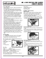
LEVELING THE TABLE ASSEMBLY
• Place a combination square on the Table so that it touches
the Abrasive Disc. If the Table is 90 degrees to the Sanding
Paper, the square should be flush on the Pad.
• If the Table is not 90 degrees, loosen the locking handle and
tilt the Table until the square is flush with the Pad.
• Tighten the Knob to secure the Table.
• Loosen the Angle Pointer Screw and adjust it so that it points
to 90 degrees.
A
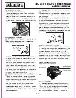
DJUSTING THE ABRASIVE BELT TRACKING
• Turn the Belt Sander on, if the Belt slides off either Roller, the
Belt Tracking needs to be adjusted to center on idler drums.
• If belt moves to the left, turn tracking nut to the right. If belt
moves to the right, turn tracking nut to the left.
• Turn the Belt Sander on again, if the Belt still slides off to one
side, continue adjusting tracking nut as needed to center belt
on drums.
ADJUSTING THE ABRASIVE BELT POSITION
CAUTION: Never make adjustments to the Belt Sander
without unplugging the plug from the electrical outlet.
• Loosen the Socket Head Bolt that is threaded into the Pivot
Bracket.
• Tilt the Belt Assembly to desired position. Secure the Belt
Assembly by tightening the Socket Head Bolt in to the Pivot
Bracket.
• Adjustable Positive Stops are provided for both horizontal
and vertical positions.
NOTE:
The horizontal limit stop is located on top of the base
and the vertical limit stop is located beneath belt cover.
ADJUSTING TABLE ANGLE
Table is used to support workpiece when sanding on the disc
or on the belt,
when the belt assembly is in the vertical position.
To adjust table angle, loosen handle (#26), tilt table to desired
position, then secure by tightening handle.
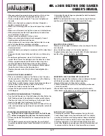
HORIZONTAL BELT SANDING WITH BACK STOP
Back stop supports the workpiece when sanding on the belt
with the belt assembly in the horizontal position.
• Remove table and stud from belt assembly.
• Tilt belt assembly from vertical to horizontal position and
secure in position.
• Mount back stop to belt assembly using the two bolts.
• Idler drum can be used as a contact drum to sand surfaces.
ABRASIVE BELT SANDING
• Finishing flat surfaces: Hold workpiece firmly with both
hands; keep fingers away from abrasive belt. Use table to
position and secure work being sanded. Keep end butted
against table and move work evenly across abrasive belt.
• Finishing long pieces: Use belt in horizontal position with
back stop. Apply only enough pressure to allow abrasive belt
to remove material. Use back stop to position and secure


