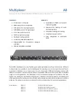
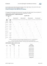
Multiplexer
5 Components of Multiplexer Package
A8
KLIPPEL Analyzer System
Page 7 of 16
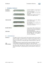
EXTERNAL MANUAL
SWITCH
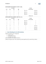
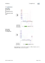
•
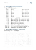
An external manual switch can be used to control the Multiplexer routing
via the DIGITAL I/O interface
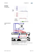
•
The switch must be active, a high signal (3 – 30 V
DC)
will cause the Multi-
plexer to change the routing
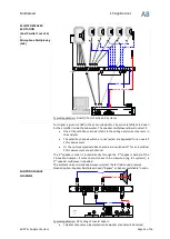
•
A toggle switch for count up/count down or two switches for the men-
tioned directions are placed at the device
Components of Multiplexer Package
The Multiplexer Package (Article Number 2800-10x) includes:
•
1 Multiplexer
•
19” Rack Mount Brackets
•
1 D-Sub 25 Cable 1.8 m
•
1 USB Cable 2 m
•
1 Power Supply with Country specific Power Cable
•
1 User Manual
•
1 Specification
•
2 Signal Cables 1 m: BNC + BNC-XLR-adapter or XLR or SPEAKON according MUX version
Safety Requirements
SIGNAL CABLE
All In / Output connections can be made with standardized cable.
SPEAKON cable must be four wire connected, if used with Klippel Distortion Ana-
lyzer, Klippel Production Analyzer or Klippel Analyzer 3.
2 signal cables for the BUS connectors are included. Cables for the inputs are in-
cluded for example in Klippel Mic Sets.
BNC, XLR, SPEAKON cable are available from Klippel.
CONTROL CABLE
USB cable and D-Sub 25 cable are included. D-Sub 37 cable is not included.
Safety Requirements
USE MULTIPLEXER ONLY
IN THE SPECIFIED WAY
KLIPPEL GmbH takes no responsibility for any kind of damage caused by the Mul-
tiplexer and improper use.


