


IOM-KHD-21E(a)-110_V1.1_EN
Copyright
©
2022 by KLINGER DIE ERSTE INDUSTRY CO., LTD.
5
4
IOM-KHD-21E(a)-110_V1.1_EN
Copyright
©
2022 by KLINGER DIE ERSTE INDUSTRY CO., LTD.
Standard 2-Piece Ball Valve
KHD-21E(a)
Standard 2-Piece Ball Valve
KHD-21E(a)
Chapter II
Installation
Flush the pipeline carefully before installing the
valve. The particles of dirt or debris or welding may
damage the ball sealing surface and seats. Also, be-
fore installing, check all valve and pipe connection to
ensure threads are free from defects.
2.1 General Notes
1) Direction
Series 21E(a) Standard 2-Piece ball valves are bi-di-
rectionally sealed unless otherwise specified.
Note:
If requested, valves with upstream hole in ball are
one-way valves.
2) Position
The body, cap and gasket are in the connection area
of ball valve and pipeline. The bear weight ability
and gradient are very important to the pipe instal-
lation. Do not make the pressure from the pipeline,
and stress to concentrate on the connecting area of
body and cap. Ball, seat, and stem will be damaged.
Consequently, deformation and leakage may occur.
Note:
Most of the valves do not restrict the flow
direction when installing the Series 21E(a) Ball
Valve. However, KLINGER DIE ERSTE suggests ver-
tical or horizontal position to maximize sealing and
reduce the accumulation. In the case of vertical
installation, upstream pressure should be locat-
ed above, since in the floating ball design, the ball
helps the sealing effects.
3) Fittings
Select the correct size of fittings according to the
pipeline specification. Mating the valve to the pipe-
line adequately with appropriate bolts. Do not at-
tempt to correct pipeline misalignment by means of
flanged bolting.
Note:
Over tightening of any side may cause leakage.
4) Systems hydrostatic test
Before delivery, valves are tested 1.5 times the al-
lowable pressure at ambient temperature in OPEN
position. However, after installation, the piping sys-
tem may subject to system tests, as condition not
to exceed the marking pressure.
5) Pre-Installation Wash
Before the valve installation, clean the pipeline sys-
tem to remove any foreign deposits by water. Clean
the connecting flanged end surfaces as well to en-
sure tight sealing.
2.2 Installation of Ends
Threaded Ends
It is not necessary to disassemble threaded end
valves before installation. Note that the taper
threaded fitting should not be over tightened.
CAUTION:
Do not exceed the valve performance limitation.
CAUTION:
Before installing, make sure the line pressure has
been relieved, and any hazardous fluids have been
drained or purged from the system.
used in the pipeline system, unless otherwise spec-
ified with the category III in Declaration of conformi-
ty.
These valves, when installed, have body connec-
tors which form an integral part of the pipeline
and the valve cannot be removed from the pipeline
without being dismantled.
1.4 Storage
If the valves are not to be installed immediately,
please store the valve carefully before installation,
preferably indoors in a dry and clean place.
Also, the valve ports should be sealed by plastic
caps to prevent dirt from entering and damaging in-
ner parts.
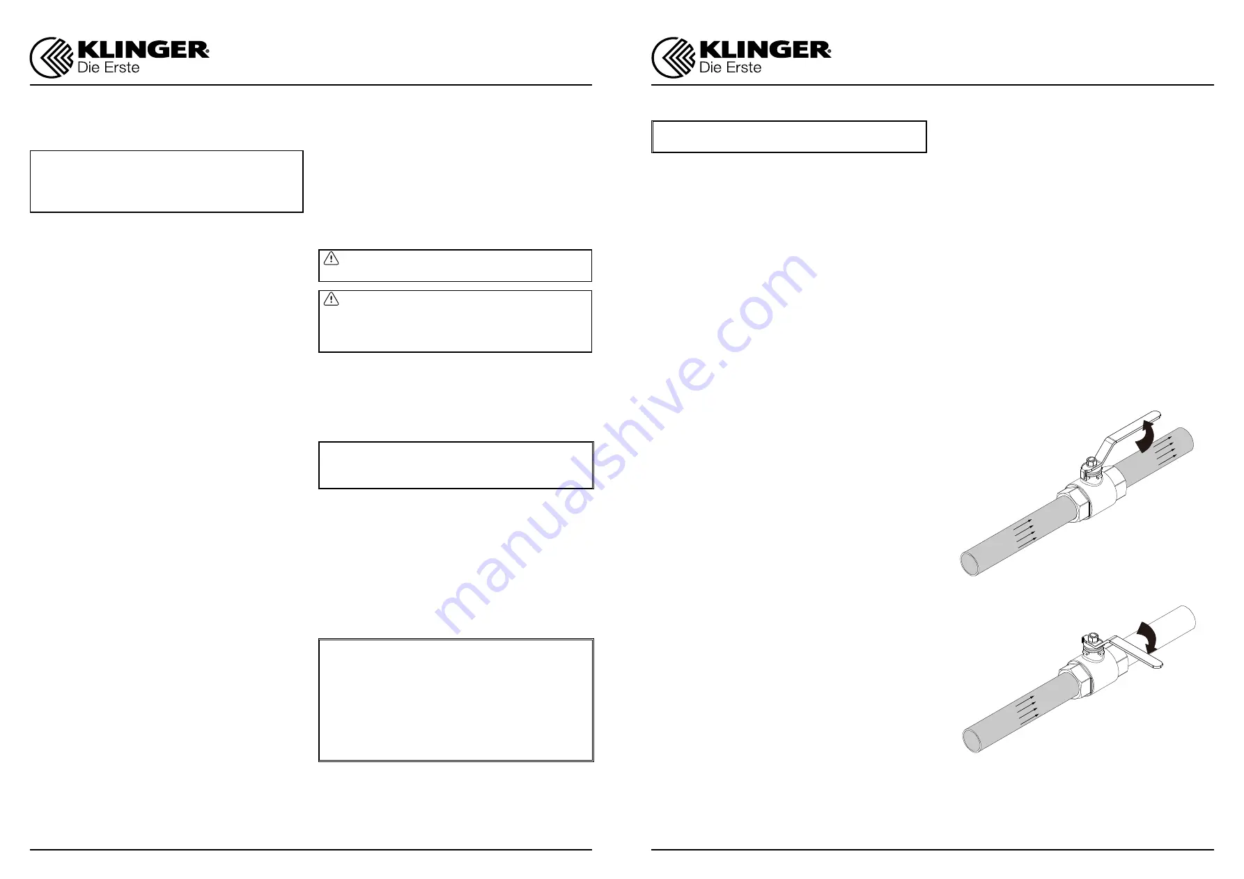
Chapter III
Operation
For manual operation, shift the handle in clockwise
direction for CLOSED and counter-clockwise for
OPEN.
If the handle is in parallel position with the flow di-
rection, the valve is OPEN. If the handle is in right
angle position with the flow direction, the valve is
CLOSED.
When installing actuator or the valve is operated
with removable handle, the user should ensure the
position of the valve whether open or close. The
Double-D orientation indicates whether the valve is
in OPEN or in CLOSED position. The below Figure 3.1
provides the visual understanding of above expla-
nation.
Figure 3.1 Rotation Direction for
CLOSED and OPEN position
CLOSE
OPEN


