


Klimawent
– the warranty of highest quality at attractive price
6 z 16
Filtering unit
BIG-2000/Ex
02.10.2019
Table No.2
– Dimensions
A
B
C
D
E
F
G
H
I
J
a
b
c
d
x
y
[mm]
[mm]
[mm] [mm]
[mm]
[mm] [mm]
[mm] [mm] [mm]
[mm] [mm] [mm]
[mm] [pieces] [pieces]
1390
960
3356 1200
1053
2550 3100
600
1320 1500
200
233
150
180
6
2
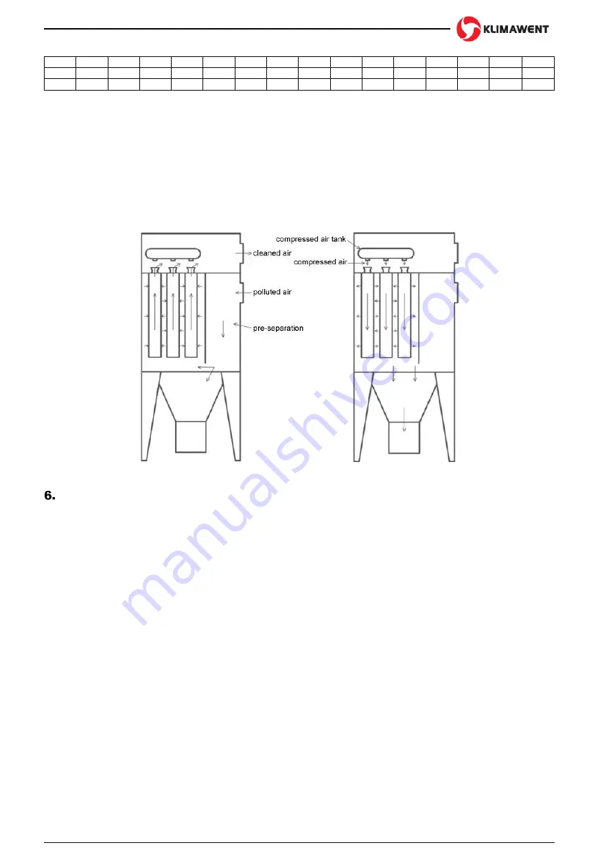
5.2 Function
BIG-2000/Ex filtering unit provides separation of the air containing dry dust fraction. The dust laden air is guided
to the chamber of filters. Here, in the decompression process and because of the flow velocity reduction, larger
particles of dust are extracted into the hopper chamber, and subsequently they fall into the waste container.
Precise dust cleaning proceeds while the air flows through the cartridge filters. In the Fig. No.5 is presented a run
diagram of the air flow through the filtering unit. As the dust accumulates on the operational surface of the cartridge
filters, this reduces the air flow intensity. To limit this disturbance, the device is equipped with a continuous
regeneration system of the filters. The impulses of compressed air (directed into the cartridge filters) strike off the
dust particles. The cleaning air is supplied from the compressed air tank, through the electromagnetic valves that
are operated by the micro-controller (in details described in Section No.7).
In the Fig. No.6 is illustrated a schematic diagram of regeneration of the cartridge filters.
Fig. No.5 Filtration scheme
Fig. No.6 Scheme of filters regeneration
ASSEMBLY AND STARTUP
6.1 Description of mounting
Before the assembly of the device in the place of use, check if the device is complete, and if it is not damaged, or
there are indentations, etc. The appliance is delivered in two assemblies, so it should be installed by means of
adequate lifting devices and by a specialised assembly team.
First, put the supporting structure with the hopper chamber. The supporting frame should be levelled and its legs
fastened firmly to the floor. Having installed the first assembly, put the chamber of filters (with the fixed to it
regeneration chamber) on it. Handle with care, as the assembly is of large dimensions. At the upper part of the
regeneration chamber are installed lifting hooks (for lifting and positioning during the transport and assembly
activities).
After the chamber of filters is connected with the supporting structure, seal up the join surface
with “silicone” and
screw it up thoroughly with bolts. The screws, bolts and “silicone” are delivered by manufacturer along with the
device.
The compressed air tank and the electromagnetic valves are delivered to the operator in completely assembled
state. Having installed the device, connect it to the external compressed air installation of 0,6
0,8 MPa. The
pressure air must not contain pollutants, oil and humidity.
The connection must be equipped with a cut-off valve, air filter and a dewaterer. These elements are not
delivered along with the device.
The nominal diameter of the compressed air connection (for the device of 2 cartridge filters and at the nominal
diameter of the compress
ed air tank of 8”) should be 1”1/2. Connection to the compressed air tank – diameter
12mm (quick-connector).
6.2 Start-up
Upon first operation of the compressed air installation (of the device), check if the connected part of the
compressed air system is sufficiently cleaned of the metal particles, rust, etc., because the membrane of the ele-
ctromagnetic valves would get damaged. If in the first stage of start-up there is not enough air flow intensity (in
the system)
– this means the valves are not tight enough. Shut the cut-off valve in the supply of the compressed
air tank. Wait until the air pressure in the system reaches 0,6
0,8 MPa, and then quickly open the cut-off valve.