klimaoprema FDC25 Series Скачать руководство пользователя страница 8

14

 | Circular fire damper user manual 03/2020

15

 | 

Circular fi

re damper user manual 03/2020

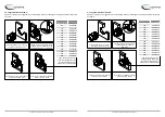
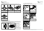
5.2.11  Installation in gypsum blocks wall 70mm

The wall is composed of gypsum blocks (minimum density of 995kg/m

³), and with minimum thickness 

of 70mm.

30

30

30

45º

30

150

150

Prepare opening in the wall 

according to dimension table (on 

page 6)

Insert fire damper into wall

Fire damper can be installed with 

minimal distance of 30 mm between 

wall, ceiling or other dampers.

Cover the mortar with GKF gypsum 

boards (12,5 mm thick)

Space between casing and wall

close with mortar

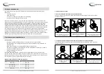
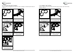
5.2.9  Installation in ceiling (Weichschott)

The ceiling is composed of aerated concrete blocks (minimum density of 550 kg/m

³) and with a 

minimum thickness of 100 mm.

Recommended ceiling opening

for fire damper installation is

Ø+ 400mm, but openings from

Ø + 80…600 mm can also be used

Insert fire damper into ceiling

Damper blade must be closed

during installation!

Space between casing and wall

close with two layers of mineral

wool (density 140 kg/m³ or more, 50 

mm thick, coated on one side)

Connections of mineral wool should be 

sealed with intumescent fire resistant sealant 

(e.g. Promastop-I or Hilti CFS-CT). Mineral 

wool and damper casing must be coated with 

2 mm thick fire protection coating

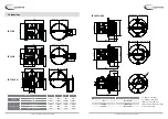
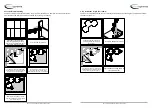
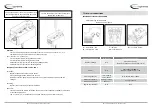
5.2.10 Suspension for mortarless installation

Suspension systems are required for the dry mortarless installation of the fire damper with mineral 

wool in solid walls, flexible walls and ceiling slabs. Fire dampers can be suspended from solid ceiling 

slabs using adequately sized threaded rods. Load the suspension system only with the weight of the 

fire damper. Ducts must be suspended separately.

1

3

2

1

4

5

Dn + 70

Dn + 70

Wall installation

Ceiling installation

Threaded rod (M10), 

galvanized steel
Washer, galvanized steel

Nut, galvanized steel
Bracket, 45x30x1,5 mm, 

galvanized steel

L shaped profile (50x50x1) 

secured with self tapping 

screw to damper housing

1

2

3

4

5

Содержание FDC25 Series

Страница 1: ... klimaoprema hr technical manual Circular fire damper FDC25 FDC40 Table of contents 1 Product presentation 2 2 Dimensional range 3 3 Dimensions 4 4 Storage and handling 6 5 Installation and implementation 6 6 Control mechanism 21 7 Electrical connections 23 8 Other mechanisms 25 9 Evolution of service kits 27 10 Maintenance 27 ...

Страница 2: ...ks wall Operating mechanism completely outside the wall Easy to install Maintenance free 1 Galvanized steel casing 2 Fire resistant damper blade 3 Control mechanism 4 Intumescent joint 5 Connection flanges 6 Product marking on the casing 7 Thermal fuse 1 Gypsum layers 2 Intumescent joint 3 Cold smoke seal 4 Boundary layer 1 3 4 5 2 6 7 1 2 3 4 2 Dimensional range In decimeters Free area for dimens...

Страница 3: ...60 45 D A 380 145 D 160 D 2 80 D 2 124 380 100 45 D D A D 380 100 45 D A D 2 80 D 2 94 FDC25 R FDC40 R FDC25 40 M FDC APPLIQUE Product A C D E Belimo BFL M 25 200 90 120 BFN M 25 225 100 120 Klimaoprema R FDC 25 55 150 105 150 R FDC 40 55 200 105 200 EMP FDC 25 40 55 200 105 200 Damper diameter ØD mm Applique frame diameter mm 100 Øn 105mm 125 180 Øn 95mm 200 315 Øn 80mm Y Øn 2 110 mm X Øn 2 270 m...

Страница 4: ...horizontal or in vertical position The installation must comply with the tests that were performed during certification as explained in 8 2 Avoid any obstruction of the moving blade by the connected ducts The class of air tightness is maintained in case the installation of the damper is made in accordance with the technical manual Operating temperature 50 C max For indoor use only The FDC25 FDC40 ...

Страница 5: ...sions and must be cut to fit the specific dimensions of the damper Diameter of the damper mm Mounting kit 100 60061429 125 60061430 160 60061431 200 60061432 250 60061433 315 60061435 355 60061436 400 60061437 450 60061438 500 60061439 560 60061440 630 60061441 710 60061442 800 60061443 Fix the damper to the wall using screws screw hole is 6mm in diameter Fill the space between the damper and the ...

Страница 6: ...h GKF gypsum boards 12 5 mm thick 625 625 440 Realization of the steel construction Place the damper in an opening according to table on pg 6 Fix the damper to the wall using screws screw hole is 6mm in diameter Fill the space between the damper and the wall with mortar Cover the mortar with GKF gypsum boards 12 5 mm thick The Kit is universal for all dimensions and must be cut to fit the specific...

Страница 7: ...12 5 mm thick installed on a 48 mm wide steel construction The interior of the wall is filled with mineral wool of 100 kg m density 700 Øn 80 Øn 80 Arrangement of steel profiles Place the damper in an opening according to table on pg 6 wall cover with gypsium plates Place ventilation duct trough wall thickness of threaded rod for suspension should be M12 or more Install fire damper and secure it w...

Страница 8: ...er into ceiling Damper blade must be closed during installation Space between casing and wall close with two layers of mineral wool density 140 kg m or more 50 mm thick coated on one side Connections of mineral wool should be sealed with intumescent fire resistant sealant e g Promastop I or Hilti CFS CT Mineral wool and damper casing must be coated with 2 mm thick fire protection coating 5 2 10 Su...

Страница 9: ... mm 30 30 30 45º 30 Prepare opening in the wall according to dimension table on page 6 Insert fire damper into wall 30 30 30 45º 30 150 150 Prepare opening in the wall according to dimension table on page 6 Insert fire damper into wall Fire damper can be installed with minimal distance of 30 mm between wall ceiling or other dampers Cover the mortar with GKF gypsum boards 12 5 mm thick Space betwee...

Страница 10: ...30 Prepare opening in the wall according to dimension table on page 6 Insert fire damper into floor Fire damper can be installed with minimal distance of 30 mm between wall ceiling or other dampers Space between casing and wall close with mortar Arrangement of steel profiles according to drawing Prepare opening in the wall according to dimension table on page 6 Insert fire damper into wall Mineral...

Страница 11: ...echanism MANUAL FUSE ONLY MECHANISM Self operating mechanism equipped with a thermal fuse The Manual fuse only control mechanism closes the damper blade automatically if the temperature in the duct exceeds 72 C The damper is reset manually by means of a screwdriver Standard equipment Thermal fuse 72 C Manual triggering is possible Manual reset use the screwdriver turn counterclockwise To open the ...

Страница 12: ...operating activation With a fuse at 72 ºC Remote activation By emission or break of current solenoid with 24 48 V automatic voltage Resetting Manual reset Turn the lever counterclockwise Reminder For this version with remote activation the double contact S OPEN CLOSED are mounted as standard equipment The 4 contact S2 are available as an option factory option or after sales kit 7 Electrical connec...

Страница 13: ...temperature sensor on the inner side of the duct temperature in the duct max 72 C Tf3 temperature sensor on the inner side of the duct temperature in the duct max 72 C Type of Belimo actuator BFL24 T BFN24 T BFL230 T BFN230 T BF24 T BF230 T Nominal voltage power con sumption voltage AC DC 24V 50 60Hz AC 24V 50 60Hz AC 230V 50 60Hz AC 230V 50 60Hz AC DC 24V 50 60Hz AC 230V 50 60Hz opening 2 5 W 4 W...

Страница 14: ... 10294 4 Passed sensing element load bearing capacity sensing element response temperature Response delay closing time according to EN 1366 2 Passed Operational reliability opening closing according to EN 1366 2 Passed Durability of response delay according to ISO 10294 4 Passed sensing element response to temperature and load bearing capacity Durability of operational reliability opening and clos...

Страница 15: ...Gradna 78A 10430 Samobor Croatia Hrvatska 385 0 1 33 62 513 info klimaoprema hr www klimaoprema hr ...

Отзывы: