


24
| Circular fire damper user manual 03/2020
25
|
Circular fi
re damper user manual 03/2020
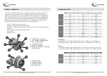
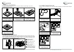
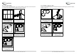
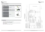
8. Other mechanism
BELIMO
Operation
Damper is delivered in closed position. When
electric actuator is connected to the power
supply damper will open. When the damper
reaches the end position (damper open), the
electromotor will stop. Closing fire damper
takes place automatically when a power failure
occurs. Thermal tripping device that comes
with fire damper causes power circuit break at
a temperature of 72 °C (inside or outside duct).
If checking is needed for proper functioning of
fire damper, pushing the switch on the thermal
tripping device will close damper. When switch
on tripping device is released, the damper will
open.
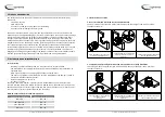
Damper can be opened without connecting
to a voltage with enclosed handle turning in
the direction of the arrow on electric actuator
(clockwise). Damper can be locked in the desired
position by fast turning back handle a quarter of
a turn (counterclockwise) for Belimo BF, and by
puling brake on Belimo BFL and BFN.
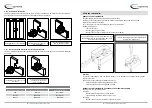
To unlock the electromotor, turn handle
clockwise for a quarter of a turn for Belimo BF,
or release brake for Belimo BFL and BFN. After
release, damper will be closed by return spring.
When damper is opened manually, electric
actuator will not move the damper into closed
position after power failure.
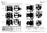
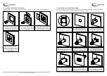
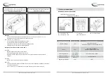
Wiring diagram
1
negative (direct-current) or neutral (alternating current)
2
positive (direct-current) or faze (alternating current)
S1
common micro switch closed damper
S2
normally closed micro switch closed damper
S3
normally open micro switch closed damper
S4
common micro switch open damper
S5
normally closed micro switch open damper
S6
normally open micro switch open damper
Tf1
temperature sensor on the outer side of the duct (ambienttemperature) max. 72°C
Tf2
temperature sensor on the inner side of the duct (temperature in the duct) max. 72°C
Tf3
temperature sensor on the inner side of the duct (temperature in the duct) max. 72°C
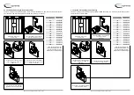
Type of Belimo actuator
BFL24-T
BFN24-T
BFL230-T
BFN230-T
BF24-T
BF230-T
Nominal
voltage /
power con
-
sumption
voltage
AC/DC 24V,
50/60Hz
AC 24V,
50/60Hz
AC 230V,
50/60Hz
AC 230V,
50/60Hz
AC/DC 24V,
50/60Hz
AC 230V,
50/60Hz
opening
2,5 W
4 W
3,5 W
5 W
7 W
8.5 W
holding
0,8 W
1,4 W
1,1 W
2,1 W
2 W
3 W
for wire sizing
4 VA
6 VA
6,5 VA
10 VA
10 VA
11 VA
End switch
1 mA...3
A (0,5 A),
DC 5 V...AC
250V
1 mA...3
A (0.5 A),
DC 5 V...AC
250 V
1 mA...3
A (0.5 A),
DC 5 V...AC
250 V
1 mA...3
A (0.5 A),
DC 5 V...AC
250 V
1 mA...6 A
(3 A), DC
5 V...AC
250 V
1 mA...3
A (0.5 A),
DC 5 V...AC
250 V
Running
time
motor
<60 s
<60 s
<60 s
<60 s
<120 s
<120 s
spring-return
~20 s
~20 s
~20 s
~20 s
~16 s
~16 s
Ambient temperature range
min. -30°C, max. 50°C
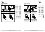
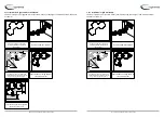
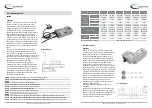
SCHISCHEK ExMax
Operation
Damper is delivered in closed position. When
electricactuator is connected to the power supply
damperwill open. When the damper reaches
the end position(damper open), in which is it
blocked, the electromotorwill stop. Closing fire
damper takes place automatically when a power
failure occurs. Thermal tripping device that
comes with fire damper causes power circuit
break at a temperature of 72 °C (inside or outside
duct). If checking is needed for proper unctioning
of fire damper, pushing the switch on the thermal
tripping device will close damper. When switch on
tripping device is released, the damper will open.
Damper can be opened without connecting to a
voltage with enclosed Allen key, by turning in the
direction of the arrow on electric actuator
(clockwise). After release of Allen key, damper
will go to closed position.
Type Examination Certificate Number: EXA 14
ATEX0064X
Equippment complies with the essential health
and safety requirements relating to the design
and construction of equippment intended to use
in potentially explosive atmospheres given in
annex II of the directive 94/9/EC..
Wiring diagram


