


SPECIAL NOTE
After installation or any servicing operation, always ensure that
the appliance is gas sound and that the components are now
operating correctly. Items removed during servicing should be
replaced in the reverse order to their
removal.
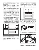
In order to change the work-top injectors,
it is necessary to act as follows:
- remove the grids
- remove burners
and flame-spreaders.
GAS ADJUSTEMENTS
- change the injectors
- adjust the minimum flow
When converting from Natural Gas to U-LPG ensure that
the NG regulator is removed and replaced with the Test Point
Assembly. A gas regulator suitable for a supply pressure of 2.75kPa
should be part of the gas tank supply and should be adjusted with
the wok burner operating at maximum.
REPLACEMENT OF THE INJECTORS
When required to operate on other gas replace the injectors in
accordance with information referred to in chart below.
6
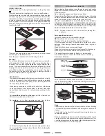
- change the injector (see Fig. C) and replace it with another one
suitable for the new type of gas (see tab. 1)
Fig. C
Z
Fig. 2B
Fig. 2A
MINIMUM FLOW ADJUSTMENT FOR HOB-TOP TAPS
In order to adjust the minimum flame setting proceed as follows:
switch the burner on, and set the knob at the minimum position
. Remove the knob from the tap, place a small bladed screwdriver
down the centre of the tap shaft (fig. 2A).
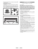
Attention:
on taps with a security valve, the minimum adjusting
screw «Z» is on the body of the gas tap (fig. 2B).
Unscrew the adjusting screw in order to increase the flow or screw
it to decrease the flow.
The correct adjustment is obtained when the flame has a length
of about 3 or 4 mm.
For butane/propane gas, the adjusting screw must be screwed
in thigt.
Make sure that the flame does not go out turning quickly from the
max. flow
to the minimum flow .
Refit the knob again.
ELECTRICAL CONNECTION
In order to avoid hazard, any electrical work performed on this
equipment or its associated wiring, should only be done by persons
authorised by the supplier or similarly qualified persons.
TAB. 1
0.53
Auxiliary 3.7
0.73 Semi-rapid
7.0
0.95
Rapid 11.7
LP Test point
adaptor
1.00 Triple Crown
12.7
U - LPG 2.75 kPa
Jet mm Ø
Burners Power MJ/h
Gas Type kPa
Natural Gas 1.00 kPa
0.90
Auxiliary 4.0
1.20 Semi-rapid
7.1
1.50
Rapid 11.0
Jet mm Ø
Burners Power MJ/h
1.63 Triple Crown
12.7
NG Regulator
Gas Type kPa
ELECTRICAL CONNECTION
The appliance must be installed by a suitably qualified person in
accordance with these instructions and with the requirements of
the Australian Wiring Rules AS/NZS 3000.
Fixed wired installations are to be provided with suitable isolation
means in accordance with the said rules.
Any plug socket installed for the purpose of connecting the
appliance to supply must be readily accessible when the appliance
is installed.
Before making the connection, make sure that:
1) the safety circuit-breaker and the electrical system are able to
withstand the load of the appliance
(see nameplate).
2) the power supply system has an earth connection in good
working order in accordance with the regulations in force;
WARNING: THIS APPLIANCE MUST BE EARTHED.
The flexible mains lead and plug must not be in contact with hot
surfaces.
IMPORTANT
The wires in the mains lead are coloured in accordance with the
following code:
GREEN & YELLOW.........................................................EARTH
BLUE...........................................................................NEUTRAL
BROWN ...............................................................................LIVE
Electric power........1,5 mm
2
core cable (15 amp. Fuse required)
Should conform to local authority requirements.
Also refer to rangehood manufacturers recommendations.
This appliance is supplied with a plug & cord, simply plug into a
3 pin household socket outlet witch is properly earthed.


