background image

11

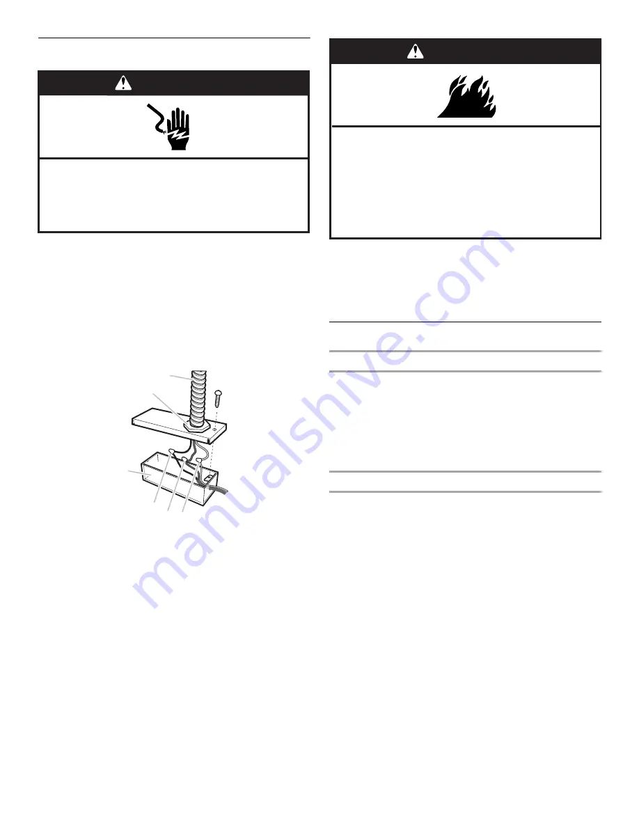
Electrical Connection

1. Disconnect power.

2. Remove terminal box cover.

3. Remove knockout from top of the terminal box and install a 

UL listed or CSA approved ½" (1.3 cm) strain relief.

4. Pull house power supply cable through the strain relief into 

the terminal box.

5. Use UL listed wire connectors and connect black wires (D) 

together. 

6. Use UL listed wire connectors and connect white wires (A) 

together.


7. Use UL listed wire connectors and connect the green (or 

bare) ground wire from the home power supply to the green 
ground wire inside the range hood terminal box. 

8. Tighten strain relief screw.

9. Install terminal box cover.

NOTE: Do not turn on power until installation is complete.

Connect the Vent System

Vented Installations

1. Replace the metal filters. See the “Range Hood Care” 

section.

2. Connect the vent system to the range hood vent opening. 

Seal the connection with clamps.

3. Reconnect power. 

4. Check the operation of the range hood fan and light. 

5. Push the range hood screen back in.

Non-Vented (recirculating) Installations

1. Connect the vent system to the range hood vent opening. 

Seal the connection with clamps. 

2. Install charcoal filters. See the “Range Hood Care” section.

3. Replace metal grease filters. See the “Range Hood Care” 

section.

4. Reconnect power. 

5. Check the operation of the range hood fan and light. 

6. Push the range hood screen back in.

To order replacement kits, see the “Assistance or Service” 
section.

A. UL listed or CSA 

approved strain relief

B. Home power supply 

cable

C. Terminal box

D. Black wires

E. Green (or bare) wire 

connected to 
yellow/green wire

F. White wires

WARNING

Electrical Shock Hazard

Disconnect power before servicing.

Replace all parts and panels before operating.

Failure to do so can result in death or electrical shock.

B

A

C

D

E

F

WARNING

Fire Hazard

Electrically ground the blower.

Use copper wire.

Connect ground wire to green ground screw in 
terminal box.

Failure to do so can result in death, fire, or 
electrical shock.

Содержание 30" (76.2 CM) SLIDE-OUT RANGE HOOD

Страница 1: ...EDE COMMANDEEXTRACTIBLEDE30 76 2CM ET36 91 4CM Instructionsd installationetGuided utilisationetd entretien Table of Contents Table des matières 2 IMPORTANT READ AND SAVE THESE INSTRUCTIONS FOR RESIDENTIAL USE ONLY IMPORTANT LIRE ET CONSERVER CES INSTRUCTIONS POUR UTILISATION RÉSIDENTIELLE UNIQUEMENT W10342488A ...

Страница 2: ...it d évacuation 27 UTILISATION DE LA HOTTE 28 Dispositifs de commande 28 Affichage 28 ENTRETIEN DE LA HOTTE 29 Nettoyage 29 Remplacement de l ampoule à halogène 29 SCHÉMAS DE CÂBLAGE 30 ASSISTANCE OU SERVICE 31 Au Canada 31 Accessoires 31 GARANTIE 32 RANGE HOOD SAFETY You can be killed or seriously injured if you don t immediately You can be killed or seriously injured if you don t follow All safe...

Страница 3: ...zardous or explosive materials and vapors CAUTION To reduce risk of fire and to properly exhaust air be sure to duct air outside do not vent exhaust air into spaces within walls or ceilings attics or into crawl spaces or garages WARNING TO REDUCE THE RISK OF FIRE USE ONLY METAL DUCTWORK WARNING TO REDUCE THE RISK OF A RANGE TOP GREASE FIRE Never leave surface units unattended at high settings Boil...

Страница 4: ...tal screws LocationRequirements IMPORTANT Observe all governing codes and ordinances Have a qualified technician install the range hood It is the installer s responsibility to comply with installation clearances specified on the model serial rating plate The model serial rating plate is located behind the filter on the left rear wall of the range hood Range hood location should be away from strong...

Страница 5: ...the elbows if more than 1 elbow is used Do not install 2 elbows together The vent system must have a damper If the roof or wall cap has a damper do not use the damper supplied with the range hood Use clamps to seal all joints in the vent system Use caulking to seal exterior wall or roof opening around the cap The size of the vent should be uniform 30 76 2 cm 30 76 2 cm model 36 91 4 cm 36 91 4 cm ...

Страница 6: ... with a maximum length of 35 ft 10 7 m For the best performance use no more than three 90 elbows To calculate the length of the system add the equivalent feet meters for each of the vent pieces used in the system Example vent system 6 15 2 cm Non Vented recirculating Installations Through the Soffit Cabinet If it is not possible to vent cooking fumes and vapors to the outside the range hood can be...

Страница 7: ...he appliance as specified on the model serial rating plate The model serial plate is located behind the filter on the rear wall of the range hood Wire sizes must conform to the requirements of the National Electrical Code ANSI NFPA 70 latest edition or CSA Standards C22 1 94 Canadian Electrical Code Part 1 and C22 2 No 0 M91 latest edition and all local codes and ordinances INSTALLATION INSTRUCTIO...

Страница 8: ...he vent opening A Remove the vent Transfer measurement A to the cabinet back wall Measure from the underside of the cabinet or wood filler strips if used Mark the cutout as shown Use a saber saw or keyhole saw to cut a round opening through the back of the cabinet and the exterior wall for the vent Go to Step 6 Non Vented recirculating Installation Through the Soffit Cabinet Measure and mark a rou...

Страница 9: ...be adjusted up for thicker cabinets or down for thinner cabinets by turning T10 TORX screw on each side of the hood 10 Place the round damper into the vent opening of the range hood and attach with 2 9 x 9 5 mm TORX screws NOTE For some non vented recirculating installations it may be easier to attach the vent system to the range hood before lifting the range hood into its final location Seal the ...

Страница 10: ...nd then pulling down the filter 7 Install a lower bracket with a 3 5 x 9 5 mm screw Be sure to position the bracket slot as shown 8 Install 2 5 x 18 mm adjusting screws 9 Place a level on either side the hood top and check the levelness of the hood front to back 10 Adjust the adjusting screws so the hood is level from front to back Repeat this procedure on the other side 11 Drill 2 3 mm pilot hole...

Страница 11: ...3 Reconnect power 4 Check the operation of the range hood fan and light 5 Push the range hood screen back in Non Vented recirculating Installations 1 Connect the vent system to the range hood vent opening Seal the connection with clamps 2 Install charcoal filters See the Range Hood Care section 3 Replace metal grease filters See the Range Hood Care section 4 Reconnect power 5 Check the operation o...

Страница 12: ...g selected Timer Control Operating the Timer To activate the timer with the fan On press TIMER An LED will begin flashing on the lower side of the display This function will the operate the hood fan for an established period of time 20 minutes if the 1 Low speed is selected 15 minutes if the 2 Medium speed is selected 10 minutes if the 3 High speed is selected 5 minutes if the P Power Boost speed ...

Страница 13: ...or Service section The charcoal filter can be cleaned and reactivated Clean the filter in the dishwasher using normal detergent and the highest temperature setting To reactivate the filter dry the filter in an oven for 10 minutes at a maximum temperature of 210 F 100 C To Install Charcoal Filter 1 For non vented recirculating installations fit the charcoal filter on the rear side of the metal grea...

Страница 14: ... V 60 Hz 230 W User Interface Main Board EMC Filter Motor Resistance Ohms Speed 1 2 3 4 BU W BU R BU GY BU BK Room Temp 45 1 Min 37 7 30 3 20 8 Max 73 4 F 23 C Y Y Y Y Y Y Y Y Y Y Y Y BK BK BK BK BK BK GY GY GY R R R R R W W W W BU BU BU W W Y G Y G Y G Y G BR BR BR BR Speed 4 Speed 3 Speed 2 Speed 1 Lamp Neutral Neutral Neutral L1 ...

Страница 15: ... United States To locate the KitchenAid designated service company in your area you can also look in your telephone directory Yellow Pages For further assistance If you need further assistance you can write to KitchenAid with any questions or concerns at KitchenAid Brand Home Appliances Customer eXperience Center 553 Benson Road Benton Harbor MI 49022 2692 Please include a daytime phone number in ...

Страница 16: ...id servicer is not available 9 The removal and reinstallation of your major appliance if it is installed in an inaccessible location or is not installed in accordance with published installation instructions 10 Major appliances with original model serial numbers that have been removed altered or cannot be easily determined This warranty is void if the factory applied serial number has been altered...

Страница 17: ...s de non respect des instructions Votre sécurité et celle des autres est très importante Nous donnons de nombreux messages de sécurité importants dans ce manuel et sur votre appareil ménager Assurez vous de toujours lire tous les messages de sécurité et de vous y conformer AVERTISSEMENT DANGER Voici le symbole d alerte de sécurité Ce symbole d alerte de sécurité vous signale les dangers potentiels...

Страница 18: ...e et évacuer adéquatement les gaz veiller à acheminer l air aspiré par un conduit jusqu à l extérieur ne pas décharger l air aspiré dans un espace vide du bâtiment comme une cavité murale un plafond un grenier un vide sanitaire ou un garage AVERTISSEMENT POUR RÉDUIRE LE RISQUE D INCENDIE UTILISER UNIQUEMENT DES CONDUITS MÉTALLIQUES AVERTISSEMENT POUR MINIMISER LE RISQUE D UN FEU DE GRAISSE SUR LA ...

Страница 19: ...ques de 3 5 x 9 5 mm Exigencesd emplacement IMPORTANT Observer les dispositions de tous les codes et règlements en vigueur Confier l installation de la hotte à un technicien qualifié C est à l installateur qu incombe la responsabilité de respecter les distances de séparation exigées spécifiées sur la plaque signalétique de l appareil La plaque signalétique de l appareil est située derrière le filt...

Страница 20: ...tiliser plus d un Ne pas installer 2 coudes successifs Le circuit d évacuation doit comporter un clapet anti reflux Si la bouche de décharge murale ou par le toit comporte un clapet anti reflux ne pas utiliser le clapet fourni avec la hotte de cuisinière Au niveau de chaque jointure du circuit d évacuation assurer l étanchéité avec les brides de serrage À l aide d un produit de calfeutrage assurer...

Страница 21: ...des d évacuation Cette hotte a été configurée à l usine pour la décharge à travers le toit ou à travers le mur Le système de décharge requis pour l installation n est pas fourni Un circuit d évacuation avec conduit circulaire de 6 15 2 cm est recommandé Calcul de la longueur effective du circuit d évacuation Pour la réalisation du circuit d évacuation on recommande un conduit de 6 15 2 cm de diamè...

Страница 22: ...y Road Cleveland OH 44131 5575 L appareil doit être alimenté par un circuit de 120 V CA seulement 60 Hz 15 A protégé par fusible Si le domicile est équipé d un câblage en aluminium suivre les instructions suivantes 1 Connecter une section de câble en cuivre massif aux conducteurs en queue de cochon 2 Connecter le câblage en aluminium à la section ajoutée de câblage en cuivre en utilisant des conne...

Страница 23: ...écouper l ouverture à travers le fond du placard 4 Si le fond du placard forme une cavité au dessus d un cadre de support on devra installer des tringles d appui en bois à droite et à gauche de l ouverture découpée afin de laisser suffisamment d espace pour pouvoir manœuvrer l élément coulissant Les cales en bois doivent être en affleurement ou en retrait de 1 6 mm à 3 2 mm par rapport au fond du ...

Страница 24: ...e soffite au dessus de la zone de la hotte Relever les mesures appropriées et tracer les lignes indiquées sur l illustration Utiliser une scie sauteuse ou scie à guichet pour découper une ouverture circulaire pour le passage du conduit d évacuation L air aspiré par la hotte peut être déchargé à l intérieur à travers le sommet du placard Pour une installation sans décharge à l extérieur recyclage l...

Страница 25: ... son emplacement final Serrer le point de connexion avec des brides Installationdelahotte 1 À l aide d au moins deux personnes soulever la hotte et la placer à son emplacement final Le câblage et le boîtier de connexion doivent se trouver au dessus de la hotte 2 Les brides de montage doivent chevaucher le fond du placard ou les tringles d appui en bois 3 Centrer la hotte 4 Installer 2 vis de monta...

Страница 26: ...ster les vis de réglage de façon à ce que la hotte soit d aplomb d avant en arrière Répéter l opération pour l autre côté 11 Percer 2 avant trous de 3 mm et installer 2 vis à bois de 4 5 x 16 mm pour fixer l avant de la hotte au bas du placard Raccordementélectrique 1 Déconnecter la source de courant électrique 2 Ôter le couvercle de la boîte de connexion 3 Ôter l opercule arrachable de la partie ...

Страница 27: ...Contrôler le fonctionnement du ventilateur de la hotte et de la lampe 5 Remettre l élément coulissant de la hotte de cuisinière en place Installation sans décharge à l extérieur recyclage 1 Connecter le circuit d évacuation sur l ouverture de décharge de la hotte Serrer le point de connexion avec des brides 2 Installer les filtres à charbon Voir la section Entretien de la hotte 3 Réinstaller les f...

Страница 28: ...ture Lorsque l écran est ouvert les lampes fonctionnent au dernier réglage sélectionné Commande de minuterie Fonctionnement de la minuterie Pour activer la minuterie alors que le ventilateur est activé appuyer sur TIMER minuterie Une DEL commence à clignoter sur la partie inférieure de l affichage Cette fonction fait fonctionner le ventilateur d évacuation pour une durée spécifique 20 minutes si l...

Страница 29: ...ttoyer et réactiver le filtre à charbon Nettoyer le filtre au lave vaisselle avec un détergent normal en sélectionnant le réglage de température le plus élevé Pour la réactivation du filtre faire sécher le filtre dans un four pendant 10 minutes à une température maximale à 210 F 100 C Installation du filtre à charbon 1 Pour les installations sans décharge à l extérieur recyclage installer le filtr...

Страница 30: ... JA JA JA JA JA JA JA JA JA JA N N N N N N GRIS GRIS GRIS R R R R R BL BL BL BL BU BU BU BL BL JA VE JA VE JA VE JA VE MAR MAR MAR MAR Vitesse 4 Vitesse 3 Vitesse 2 Vitesse 1 Lampe Neutre L1 Caractéristiques de moteur Alimentation électrique Fréquence Puissance absorbée 120 V 60 Hz 230 W Résistance moteur Ohms Temp ambiante Transformateur Interface utilisateur Neutre Neutre ...

Страница 31: ...s sujets suivants Caractéristiques et spécifications sur toute notre gamme d appareils électroménagers Consignes d utilisation et d entretien Vente d accessoires et de pièces de rechange Références aux marchands locaux aux distributeurs de pièces de rechange et aux compagnies de service Les techniciens de service désignés par KitchenAid Canada sont formés pour remplir la garantie des produits et f...

Страница 32: ... aux instructions d installation fournies 10 Les gros appareils ménagers dont les numéros de série et de modèle originaux ont été enlevés modifiés ou qui ne peuvent pas être facilement identifiés La présente garantie est nulle si le numéro de série d usine a été modifié ou enlevé du gros appareil ménager Le coût d une réparation ou d un remplacement dans le cadre de ces circonstances exclues est à...

Отзывы: