


Chapter 4. Display
4-7
Enter Key saves the new value.
The value for
Brite
is selected while in the
menu tree for
any
channel and applies to
all
of the channels in the system.
Time
Time and date are set, displayed, and
enabled in this menu. Accuracy is better than
+/- 1 minute per month, and timekeeping is
maintained for more than 10 years without
power. The date and time are included on
printed output from the Weigh II, so setting
and enabling these functions can help you
maintain good documentation on vessel
contents.
When in the
Set
Menu, the number/character
displayed directly to the right of the flashing
cursor is modified with the Up and Down
Arrow Keys. Pressing the Enter Key ad-
vances the cursor to the next number/
character field. Pressing the Esc Key when
completed setting the time and date enters
the values in memory. Once set, the clock
must be enabled to function. On the display,
an asterisk indicates whether
Enab
is
On
or
Off
.
Time
is set while in the menu tree for
any
channel and applies to
all
of the channels in
the system.
Zclmp
This menu allows the user to set a window
around zero for the gross weight. When the
gross weight value falls within the specified
range (usually indicating a negligible amount
of material in the vessel), the display is forced
to zero.
The user can specify a different range for
gross weight above zero (
Hi
value) and gross
weight below zero (
Lo
value). For example, if
the user enters a Lo value of -200 and a Hi
value of 100, all measured gross weights
between -200 and +100 will appear as zero
on the display. If you do not set a non-zero
Lo
value, the display may show a small negative
gross weight when the vessel is near empty if
the calibration of the system is not 100
percent accurate. The
Zclmp
function only
affects the value seen on the display. Set-
points, current outputs, and serial outputs are
unaffected.
Hi
can range from 0 to 255;
Lo
can range
from 0 to -255. The default values for both are
0. The values can be modified by using the
Up and Down Arrow Keys or by direct entry
with the Alphanumeric Keys. When the
desired number is shown, pressing the Enter
Key saves the new value.
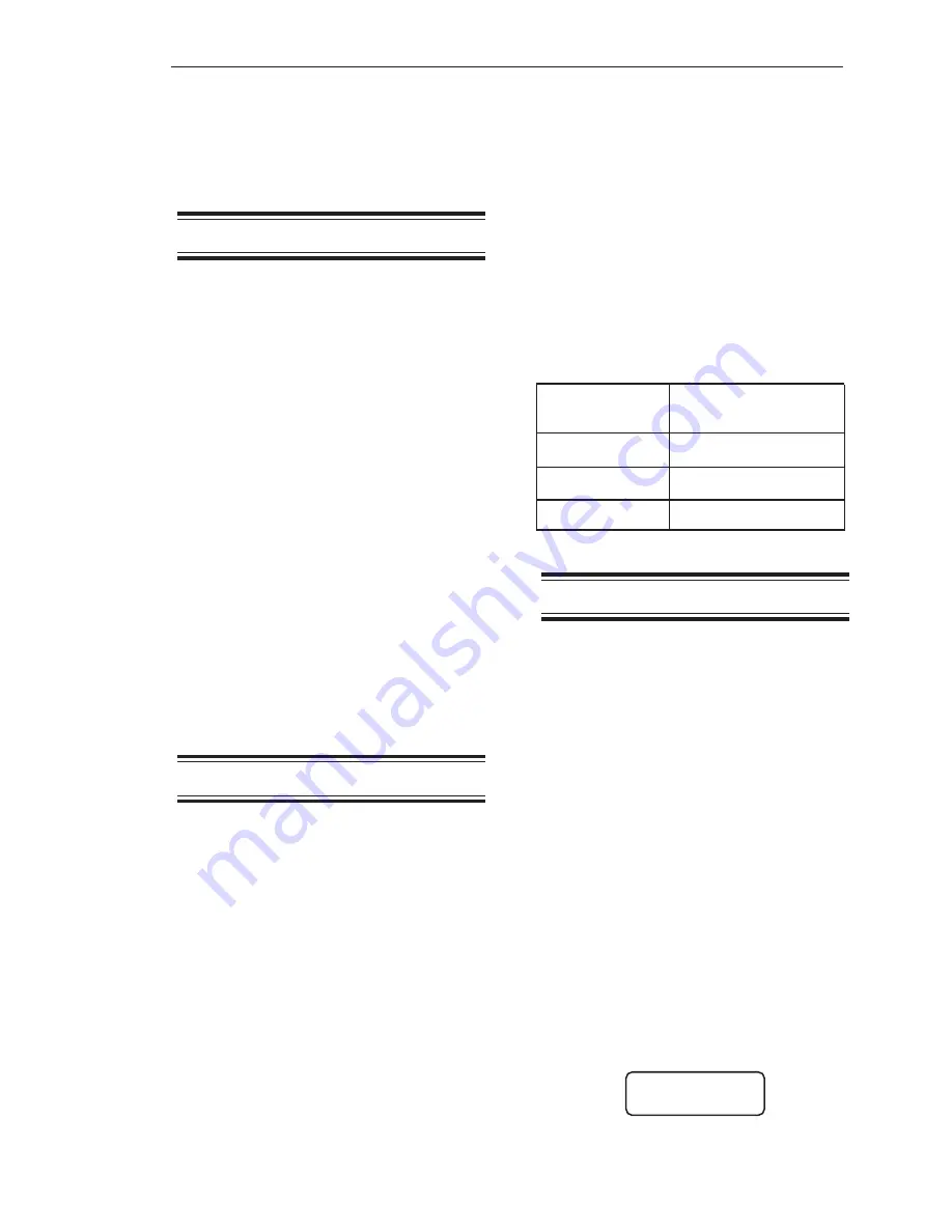
Note that when you input the value for
Zclmp
,
the display automatically shows any fixed
zeroes or decimal point, consistent with your
selection for
Form
. Table 4-2 shows some
examples of the maximum value for Zclmp.
Form
Maximum Value
for
Zclmp
xxx.xx
2.55
xxxxx
255
xxxxxoo
25500
Table 4-2. Interaction of Form and Zclmp
Hide
This menu allows you to ‘hide’ a channel(s)
from the scanning sequence on the display.
The Weigh II continues to monitor the
channel(s) that is hidden, but does not
display it. This function is useful if you are not
using all of the available channels to monitor
vessels, want to observe specific channels
without taking the other channels in the
system off-line, or want to hide math
channel(s) that contain intermediate results.
The default for
Hide
is
Off
(i.e., the channel is
not hidden).
Follow this procedure to hide channels.
1. If the Weigh II is in Auto Mode (Auto LED
illuminated), press the Auto/Man Key to
put the system in Manual Mode. The Auto
LED turns off.
2. Use the Up Arrow or Down Arrow Keys to
scroll to the desired channel.
3. Press the Menu Key to display the
Main
Menu. The display shows:
WII MAIN MENU
Disp I/O Cal
F1 F2 F3
Содержание Weigh II
Страница 12: ...2 4 Chapter 2 Hardware Installation...
Страница 20: ...3 8 Chapter 3 Menu Tree Keyboard Functions and Quick Start...
Страница 50: ...6 12 Chapter 6 Calibration...
Страница 68: ...A 2 Appendix A Product Specifications...
Страница 70: ...B 2 Appendix B Summary of Commands Used When Vessel Mounting Hot Keys...
Страница 77: ...Appendix E E 1 This appendix not used at this time...
Страница 78: ...Appendix E E 2...
Страница 80: ...Appendix F Technical Drawings F 2...
Страница 81: ...Appendix F Technical Drawings F 3...
Страница 82: ...Appendix F Technical Drawings F 4...
Страница 83: ...Appendix F Technical Drawings F 5...
Страница 84: ...Appendix F Technical Drawings F 6...
Страница 85: ...Appendix F Technical Drawings F 7...
Страница 86: ...Appendix F Technical Drawings F 8...
Страница 87: ...Appendix F Technical Drawings F 9...
Страница 88: ...Appendix F Technical Drawings F 10...
Страница 89: ...Appendix F Technical Drawings F 11...
Страница 90: ...Appendix F Technical Drawings F 12...
Страница 91: ...Appendix F Technical Drawings F 13...
Страница 92: ...Appendix F Technical Drawings F 14...
Страница 93: ...Appendix F Technical Drawings F 15...
Страница 94: ...Appendix F Technical Drawings F 16...
Страница 95: ...Appendix F Technical Drawings F 17...
Страница 96: ...Appendix F Technical Drawings F 18...
Страница 97: ...Appendix F Technical Drawings F 19...
Страница 98: ...Appendix F Technical Drawings F 20...
Страница 99: ...Appendix F Technical Drawings F 21...
Страница 100: ...Appendix F Technical Drawings F 22...
Страница 101: ...Appendix F Technical Drawings F 23...
Страница 102: ...Appendix F Technical Drawings F 24...
Страница 103: ...Appendix F Technical Drawings F 25...
Страница 104: ...Appendix F Technical Drawings F 26...
Страница 105: ...Appendix F Technical Drawings F 27...
Страница 106: ...Appendix F Technical Drawings F 28...
Страница 107: ...Appendix F Technical Drawings F 29...
Страница 108: ...Appendix F Technical Drawings F 30...
Страница 109: ...Appendix F Technical Drawings F 31...
Страница 110: ...Appendix F Technical Drawings F 32...
Страница 116: ...Appendix G Calculation of Maunal Calibration Parameters G 6...


