


PT6800 Service Manual
2
flashes red while in low battery power.
B. On/Off/Volume Control Knob
Rotate clockwise till a sound of click is produced to turn on
the radio; and rotate anticlockwise till a sound of click is
produced to turn off the radio. Rotate this knob to adjust the
volume while the radio is on.
C. Rotary Encoder
Rotate this knob to select your desired call address or
features for setting.
D. Antenna
E. Emergency Button
Press it to enable the “Emergency Call” function.
F. Clear Button
Press to return to Trunking Mode while in Conventional
Mode, or to end a call.
G. PTT (Push-To-Talk) Button
Press to call or transmit voice.
H. Redial/Monitor Button
Press to redial a number or monitor the channel.
I. “ ”
Key
Press to enter the Menu Mode.
J. “
” Key
Scroll upwards to view the previous page.
K. “
” Key
Scroll downwards to view the next page.
L. “
” Key
Press to view status messages or data messages.
M. Numeric Keypad
Press to input the call address or dial a number.
N. Universal Connector
Connect to earphone or optional speaker/microphone.
2.2 Display Screen
Icon
Description
Indicates the signal strength.
SVC
Appears when a control channel is found. Flashes while
the radio is hunting for a control channel. (Trunking
Mode only)
MON Appears while you are monitoring a channel by pressing
the Monitor button. (Conventional Mode only)
SCN
Appears while you are scanning. (Conventional Mode
only)
Lo
Appears when the transmitting power is low.
Appears when you are in home system, and disappears
when in roaming. (Trunking Mode only)
Appears when there is new data received, including
voice message, digital data message and missed calls.
(Trunking Mode only)
Appears when you are in roaming. (Trunking Mode
only)
Appears when the keypad is locked.
Appears when the Rotary Encoder is locked.
Appears when the setting is not All Mute, and the ring
alert function is active.
Indicates the current battery power level, and flashes
when the battery power is low.
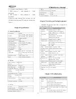
Chapter 3 Mode Introduction
3.1 Mode Introduction
Mode
Function
How to Enter
Trunking
Mode
Press the Clear Button to return to
Trunking Mode while in
Conventional Mode.
User
Mode
Conventional
Mode
For normal use.
Press
“
”
key to enter
Conventional Mode while in
Trunking Mode. Or press the
combination keys set in PC
software to switch between the
two modes.
Panel Test Mode
Used by the
dealer to check
the fundamental
characteristics.
Press and hold “
”
key while
turning the radio power ON.
Panel Tuning Mode
Used by the
dealer to tune the
radio.
Press and hold “
” key while
turning the radio power ON.
Version Information
Mode
Used to check
the version.
Press and hold “
” key while
turning the radio power ON.
PC Test Mode
Used to tune the
radio by PC.
Run KSP6800 programming
software. Click “Program” in the
main menu, and then click “Test
Mode” in the pull-down menu.
3.2 Panel Test Mode
Please refer to Chapter 7 Adjustment.
3.3 Panel Tuning Mode
Please refer to Chapter 7 Adjustment.
3.4 PC Test Mode
Содержание PT6800
Страница 28: ...PT6800 Service Manual 27 Figure 3 PT6800 Main Board Top Layer Position Mark Diagram ...
Страница 29: ...PT6800 Service Manual 28 Figure 4 PT6800 Main Board Bottom Layer Position Mark Diagram ...
Страница 30: ...PT6800 Service Manual 29 Figure 5 PT6800 Main Board Top Layer Position Value Diagram ...
Страница 31: ...PT6800 Service Manual 30 Figure 6 PT6800 Main Board Bottom Layer Position Value Diagram ...
Страница 33: ...PT6800 Service Manual 32 Figure 8 PT6800 Key Board Top Layer Position Mark Diagram ...
Страница 34: ...PT6800 Service Manual 33 Figure 9 PT6800 Key Board Bottom Layer Position Mark Diagram ...
Страница 35: ...PT6800 Service Manual 34 Figure 10 PT6800 Key Board Top Layer Position Value Diagram ...
Страница 36: ...PT6800 Service Manual 35 Figure 11 PT6800 Key Board Bottom Layer Position Value Diagram ...
Страница 40: ...PT6800 Service Manual 39 Figure 16 KBC 60Q Schematic Circuit Diagram ...
Страница 41: ...PT6800 Service Manual 40 Figure 17 PCB Layout 1 ...
Страница 42: ...PT6800 Service Manual 41 Figure 18 PCB Layout 2 ...


