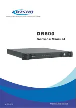
DR600 Service Manual
1. Overview
1.1 Scope of Manual
This manual is intended for use by trained engineers and professional technicians for the maintenance and
repair of DR600 Repeater. Data changes in this manual may occur with the improvement of technology. To
get the latest technology information, please contact us or your local distributors.
Before repairing the unit, please read this manual.
1.2 Safey Precautions
Electromagnetic Radiation
Radios generate and radiate electromagnetic energy, the security design of Kirisun radios’ electromagnetic
radiation on human meets national and international standards.
Electromagnetic Interference
Installation should be in accordance with local radio regulations.
Explosive and Harmful Gases
Do not install the repeater in areas with explosive and harmful gases, such as the lower deck of the hull,
fuel or chemical storage facilities, area where the air contains chemicals or particles, dust or metal dust.
Do not install the repeater when close to the blasting area, electric blasting detonators.
Replacement Parts
When replacing any replacement part, please be aware of the model. Do not arbitrarily replace the
component that does not match with the radio.
1
Содержание DR600
Страница 1: ......
Страница 37: ...DR600 Service Manual 33 ...
Страница 109: ...DR600 Service Manual Appendix 2 PCB View and Schematic Diagram Figure 1 Rx Module Top Board PCB View 105 ...
Страница 110: ...DR600 Service Manual Figure 2 Rx Module Bottom Board PCB View 106 ...
Страница 111: ...DR600 Service Manual Figure 3 Tx Module Top Board PCB View 107 ...
Страница 113: ...DR600 Service Manual Figure 6 Baseband Mainboard Top Board PCB View 109 ...
Страница 114: ...DR600 Service Manual Figure 7 Baseband Mainboard Bottom Board PCB View 110 ...
Страница 115: ...DR600 Service Manual Figure 8 Front Panel Top Board PCB View Figure 9 Front Panel Bottom Board PCB View 111 ...
Страница 116: ...DR600 Service Manual Figure 10 Power Board Top Board PCB View 112 ...
Страница 117: ...DR600 Service Manual Figure 11 Accessory Board Top Board PCB View Figure 12 Accessory Board Bottom Board PCB View 113 ...
Страница 118: ...DR600 Service Manual Figure 13 Enternet Board Top Board PCB View 114 ...
Страница 119: ...DR600 Service Manual Figure 14 Enternet Board Bop Board PCB View 115 ...
Страница 150: ...DR600 Service Manual Figure 21 Baseband Mainboard Schematic Diagram 146 ...


