DP990/DP995service manual
15
5.5.Detaching Main Board from Aluminum-Alloy Holder
Step 1 Screw down the eight screws on the mainboard using a Phillips screwdriver.
Step 2 Unsolder the motor wire using a soldering iron, and then take down the motherboard.
5.6.Detaching Key Board
Step 1 Insert the thin point of a flat-headed screwdriver into the gap between the volume and channel knobs and the
top housing, and prize and pull out the knobs.
Step 2 Remove the nut of the volume knob using a special tool.
Step 3 Unplug the FPC cables of the earphone board, numeric keys, PTT key from the sockets on the key board.
Step 4 Unsolder the leads of the speaker and mic using a soldering iron.
Step 5 Take down the four screws on the key board, and then take off the board.
After the above disassembly procedures are finished, you may repair and debug the radio.
Содержание DP990
Страница 7: ...DP990 DP995service manual 6 3 Circuit Description 3 1 Overall Circuit ...
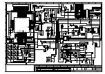
Страница 49: ...DP990 DP995service manual 48 Figure 5 Schematic Diagram of Main Board ...
Страница 50: ...DP990 DP995service manual 49 ...
Страница 51: ...DP990 DP995service manual 50 ...
Страница 52: ...DP990 DP995service manual 51 ...
Страница 53: ...DP990 DP995service manual 52 ...
Страница 54: ...DP990 DP995service manual 53 ...
Страница 55: ...DP990 DP995service manual 54 Figure 6 Schematic Diagram of Key Board ...
Страница 69: ...DP990 DP995service manual 68 Figure 5 Schematic Diagram of Main Board ...
Страница 70: ...DP990 DP995service manual 69 ...
Страница 71: ...DP990 DP995service manual 70 ...
Страница 72: ...DP990 DP995service manual 71 ...
Страница 73: ...DP990 DP995service manual 72 ...
Страница 74: ...DP990 DP995service manual 73 ...
Страница 75: ...DP990 DP995service manual 74 Figure 6 Schematic Diagram of Key Board ...
Страница 76: ...DP990 DP995service manual 75 ...


