Kipp & Zonen CNR 4 Скачать руководство пользователя страница 10


1.1.6


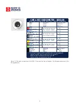
Using the CNR 4 measuring Net Radiation 


In  the  CNR  4  all  components  are  measured  separately.  This  implies  that  you  should  connect  all  individual 
radiometers  and  one  of  the  temperature  sensors.  The  two  pyranometers  will  measure  the  solar  radiation,  both 
incoming  and  reflected,  the  two  pyrgeometers  will  measure  the  Far  Infrared  radiation.  For  proper  analysis  of  the 
pyrgeometer measurement results, they must be temperature corrected using the temperature measurement. The 
following  paragraphs  describe  how  you  should  treat  the  instrument,  and  how  different  parameters  like  net  Solar 
radiation, net Far Infrared radiation, soil temperature, sky temperature, and Net (total) radiation can be calculated.  
Because all radiometers have different sensitivities it is not possible to interconnect the outputs to get the total Net 
Radiation. 


1.1.6.1 

Measuring Solar radiation with the pyranometer 


Measuring with a pyranometer can be done by connecting two pyranometer wires, + and -, to a voltmeter. Incidental 
light  results  in  a  positive  signal.  The  pyranometer  mounting  plate  and  ambient  air  should  be  at  the  same 
temperature, as much as possible. Conversion of the voltage to irradiance can be done according to equation 1.1. 
This  is  sometimes  done  in  the  data  logging  system  itself,  sometimes  during  evaluation  in  the  user's  software. 
Measuring with the upward-facing pyranometer, the so-called global (solar) radiation is measured. The downward-
facing  pyranometer  measures  the  reflected  solar  radiation.  When  calculating  the  Net  radiation,  the  Reflected 
radiation must be subtracted from the global radiation. See 1.1.6.5. 


1.1.6.2 

Measuring Far Infrared radiation with the pyrgeometer 

 
A measurement with the pyrgeometer can be performed by connecting two pyrgeometer wires, + and -, to a voltme-
ter. A signal radiating from a source which is warmer than the pyrgeometer results in a positive signal.  
 
To measure the Far Infrared irradiances with the two pyrgeometers, separately the Pt-100 output is required. The 
formula 1.2 is used to calculate the Far Infrared irradiance of the sky and of the ground. 
With the downward-facing pyrgeometer, you would generally measure the Far Infrared radiation that is emitted by 
the ground. In contrast, the upward-facing pyrgeometer is generally used to measure the Far Infrared radiation from 
the sky. As the sky is typically colder than the instrument, you can expect negative voltage signals from the upward-
facing pyrgeometer.


1.1.6.3 

Measuring the CNR 4's body temperature 


The CNR 4 has two temperature sensors built in as standard. The main reason to choose between the Pt-100 or the 
Thermistor is the connected data logger. 
 
Some data loggers have inputs for thermistors some only for thermistors some have both. 
Check carefully the correct sensor regarding to the data logger. There is no difference in accuracy. 
The Pt-100 however can be used in 4 wire mode as is therefore compensated for longer wires. 
The  Thermistor  has  itself  higher  impedance  (10k)  and  is  less  susceptible  for  longer  wires,  but  can  not  be 
compensated for it. 
 
To obtain a signal from the Pt-100, a current of about 1 mA is fed through two wires on either side of the PT-100. 
The voltage that is generated must be measured using the other pair of wires which are connected in parallel with 
the  PT-100.This  is  known  as  a  4-wire  measurement.  Measuring  in  this  manner  eliminates  errors  during  measure-
ment, which would be produced by additional wire length. Some systems have a 3-wire connection. In this case omit 
one  current  lead  and  follow  the  instructions  of  your  measurement  system  manual.  Table  1.1  states  the  Pt-100 
resistance  values  as  a  function  of  temperature.  Please  note  that  for  use  in  formula  1.2,  you  must  use  Kelvin,  not 
degrees Celsius or Fahrenheit. Most data acquisition systems have standard readout and conversion for Pt-100's. . 
The thermistor resistance values as a function of temperature are indicated in table 1.2. 


Содержание CNR 4

Страница 1: ...Net Radiometer CNR 4 Instruction Manual...

Страница 2: ...LITY Kipp Zonen guarantees that the product delivered has been thoroughly tested to ensure that it meets its published specifications The warranty included in the conditions of delivery is valid only...

Страница 3: ...nder our sole responsibility that the product Type CNR 4 Name Net Radiometer To which this declaration relates is in conformity with the following standards Imissions EN 50082 1 Group standard Emissio...

Страница 4: ...f the pyranometer 18 2 2 2 Spectral properties of the pyranometer 20 2 2 3 Directional Cosine response of the pyranometer 20 2 3 Properties of the pyrgeometer 22 2 3 1 Window heating offset 22 2 3 2 W...

Страница 5: ...ient air flow over the domes and windows to minimize the formation of dew and reduce the frequency of cleaning The integrated heater can be used to melt frost The CNR 4 specifications when used with C...

Страница 6: ...as also 8 pins but only 6 wires are coming out of the cable Exchanging the connectors will not damage the CNR 4 To prevent mix up of the cables after installation it is advised to mark the cables with...

Страница 7: ...rgeometer Upper Oben Sup rieur Superior Pyrgeometer Lower Unten Inf rieur M s bajo Blue Blau Bleu Azul Connect with Anschluss an Relier Conectar con Yellow Gelb Jaune Amarillo Green Gr n Vert Verde Ho...

Страница 8: ...d covered with a black sleeve If the CNR 4 rod is grounded to the mast it is advised not to connect the shielding on the data logger side This might cause ground loops and offsets in the signal Figure...

Страница 9: ...ween the pyrgeometer and the object that it is facing This implies that the pyrgeometer will generate a positive voltage output V when it faces an object that is hotter than its own sensor housing and...

Страница 10: ...in a positive signal To measure the Far Infrared irradiances with the two pyrgeometers separately the Pt 100 output is required The formula 1 2 is used to calculate the Far Infrared irradiance of the...

Страница 11: ...39 100 78 101 17 101 56 101 95 102 34 102 73 103 12 103 51 103 90 104 29 104 68 105 07 105 46 105 85 106 24 106 63 107 02 107 40 107 79 108 18 108 57 108 96 109 35 109 73 110 12 110 51 110 90 111 28...

Страница 12: ...2952 2854 Table 1 2 Resistance values versus temperature in C of the CNR 4 s thermistor Relatively small errors occur when the CNR 4 is not in thermal equilibrium This happens for example when the hea...

Страница 13: ...pyranometer E lower pyranometer 1 4 In this formula E is calculated according to formula 1 1 Net Solar radiation will always be positive Checking this can be used as a tool for quality assurance of y...

Страница 14: ...ature column nine tracks the ambient temperature Under cloudy conditions this is logical cloud bases will be colder than the ambient temperature at instrument level the temperature difference depends...

Страница 15: ...e upper pyrgeometer Figure 1 2 3 clear day for the downward facing pyrgeometer Upper pyrgeometer day with alterna3ng cloud elds pyrgeometer U_emf Sensi3vity W m Temp YSI 44031 C Upwelling signal downw...

Страница 16: ...cooling The sky and the ground temperature can be calculated from the measured values of the sensors using formulas 1 6 and 1 7 day night Cloudy clear 20 C 20 C pyrgeo Up pyrgeo low pyrano up pyrano...

Страница 17: ...g improve the accuracy significantly Due to the fact that the Net Solar radiation can be very intense 1000 Watts per square metre compared to a typical 100 for the Net Far Infrared radiation the accur...

Страница 18: ...ature C 40 to 80 CE according to EC guideline 89 336 EEC 73 23 EEC Environmental protection IP 67 2 2 Properties of the pyranometer The pyranometer consists of a thermopile sensor and a glass dome bot...

Страница 19: ...sensitivity N S 40 C to 10 C 4 10 C to 40 C N S 40 C to 80 C Definition Maximum error due to any change of instrument temperature within the indicated temperature interval Tilt error 1 Definition Max...

Страница 20: ...nition Deviation of the product of spectral absorption and spectral transmittance from the corresponding mean within the indicated spectral range Uncertainty in daily total 5 95 confidence level Defin...

Страница 21: ...t absorbs all radiation from all wavelengths Its field of view is 180 degrees The directional properties are similar to that of a blackbody Another way of expressing these directional properties is to...

Страница 22: ...sponse or cosine response of the pyranometer On the horizontal axis the zenith angle is shown 0E zenith angle equals 90E angle of incidence The vertical axis shows the deviation from the ideal cosine...

Страница 23: ...range This error is neglected however in the net radiation calculation this is justified because the solar radiation is always dominant when this error occurs Due to its construction the window heatin...

Страница 24: ...indow heating offset W m 6 0 to 1000 W m solar irradiance Definition Caused by heating of the dome due to solar radiation Field of view Upper detector Lower detector 180 150 Definition Sensor opening...

Страница 25: ...ectivity of the total instrument 2 3 5 Directional Cosine response of the pyrgeometer The measurement of the Far Infrared radiation falling on a surface also called irradiance or radiative flux requir...

Страница 26: ...e significant Dew deposition will probably take place under conditions with large Far Infrared irradiation from the pyrgeometer detector to the clear sky typically minus 100 Watts per metre square Und...

Страница 27: ...A table stating the resistance values can be found in table 1 1 The thermistor has a much larger resistance value than the Pt 100 also the change in resistance with respect to temperature in absolute...

Страница 28: ...librated against the World Reference at WMO in Davos 3 3 Recalibration of pyranometers and pyrgeometers We suggest recalibration for all sensors pyranometers and pyrgeometers to be performed every two...

Страница 29: ...nt by less than 1 The Net Radiometer should be installed horizontally using the level on the body of the CNR 4 For installation in buildings or in solar energy applications you will often have to moun...

Страница 30: ...or cover black part in picture below can be removed by just pulling it down from the CNR 4 The filter needs to be checked for dust and particles every 6 12 months It can be cleaned by simply washing i...

Страница 31: ...e starting the second test measurement let the pyranometer rest for at least five minutes to let it regain its thermal equilibrium For testing set a voltmeter to its most sensitive range setting Darke...

Страница 32: ...ermistor Using a meter which measures resistance you can check the operation of the thermistor If connected properly the resistance of two wires of the thermistor should be measured The value can be r...

Страница 33: ...bject The top U bolts allow rotation of the CNR 4 rod while the extra screw under the front U bolt allows the rod to tilt All mounting material for fixation to a horizontal or vertical pole is include...

Страница 34: ...33 Fig 7 2 CMB 1 mounting examples with CNR 4 albedometer and pyranometer...

Страница 35: ...clude the following items A delivery includes One CNR 4 One mounting rod Two cables Two drying cartridges Four calibration values on 2 calibration sheets long and short wave One CD with instruction ma...

Страница 36: ...Here recalibration to the highest standards can be performed at low cost Recalibration can usually be performed within four weeks If required urgent recalibration can be accomplished in three weeks or...

Страница 37: ...ro de repuestos Passion for Precision Go to www kippzonen com for your local distributor or contact your local sales office HEAD OFFICE Kipp Zonen B V Delftechpark 36 2628 XH Delft P O Box 507 2600 AM...

Отзывы: