36
FPW Collector Installation Manual
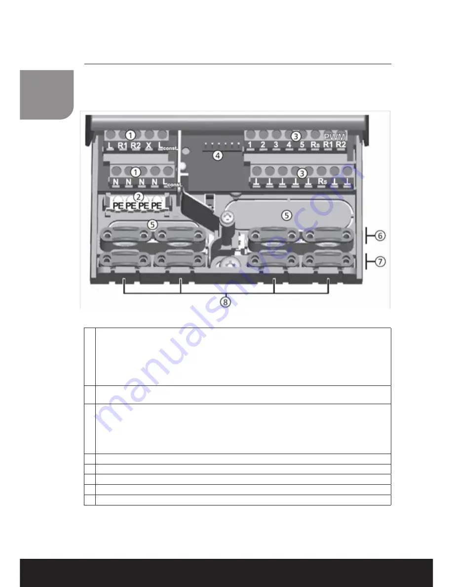
Wiring the Solar Control Panel
Wiring layout for SC400 and SC500 only
1
Power connection terminal block
L: 1x phase conductor (mains input)
R1, R2: 2x output (TRIAC, for pumps or valves)
X: not used
Lconst.: 2x phase conductor (outputs, permanent voltage)
N: 4x neutral conductor (common neutral conductors for mains power input and outputs)
Note: Outputs R1 and R2 are protected by an electronic fuse.
2
Protective conductor terminal block:
PE 4x protective earth (common protective earth for power connection) terminal block
3
Signals terminal block:
1 – 4: 4 x sensor input (Pt1000 temperature sensor)
5: 1 x sensor input (Pt1000 temperature sensor or pulse water meter input)
RS: 1 x signal output (potential-free relay contact for safety extra-low voltage)
PWM R1, R2 2 x control output (for PWM-controlled high-efficiency pumps)
7 x mass connection (common mass for sensor inputs and control outputs)
4 Pin strip, for internal use only
5 Cable openings on the rear side of the casing
6 Upper strain relief clamps (2 identical plastic links, each with 2 strain relief clamps, supplied in the scope of delivery)
7
Lower strain relief clamps
8 Cable openings at the bottom of the casing
Содержание FPW18
Страница 1: ...SolarThermalEnergy T 44 0 28 3836 4520 www kingspanthermomax com FPW FLAT PLATE INSTALLATION MANUAL...
Страница 17: ...15 In roof Mounting 19 1 6 20 6 1 6 1 6 1 6 1 21 Bend the flaps on the left sidepart as shown in pict 20 21...
Страница 21: ...19 In roof Mounting 33 8 8 32 8 Fix the bent flaps with 2 rivets 31 8 8...
Страница 33: ...31 Flat Plate Connection Kit KFP0067 1 ISO228Rp 3 4 to G 3 4 2 3 4 washers 3 Stop end...
Страница 46: ......
Страница 47: ......


