ADJUSTMENTS
REMOVING TAbLE INSERT
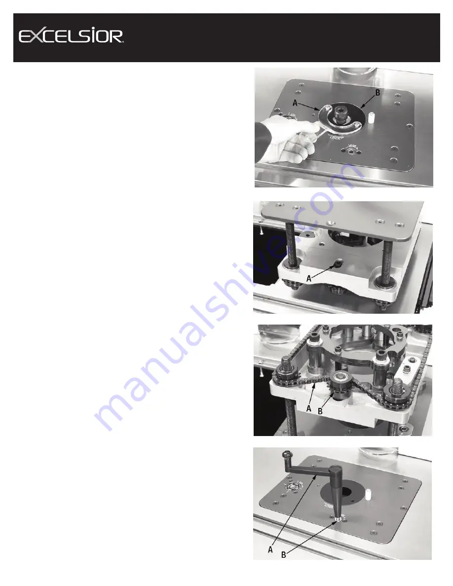
1) The Router Lift comes with a table insert wrench (A) Fig.9 and it is used
to lock or remove the table insert (B) from the Router Lift top plate. Posi-
tion the two pins of the wrench inside the two holes in the table insert.
Turn wrench clockwise to unlock and remove the table insert, turn
wrench counterclockwise to lock table insert to top plate.
Optional table insert kits are available for this Router Lift as follows:
• 4 pc. Zero Clearance Insert Ring Kit (optional- model XL-074)
• 4 pc. Insert Ring Kit- Openings: 1/4”, 1/2”, 1-3/8”, 2-1/2” (optional- model
XL-076)
TENSIONING THE DRIVE CHAIN
In combination with the brake of the Router Lift, it is important to make sure
the drive chain is always properly tensioned to avoid any chance of the
router creeping or the brake from working improperly.
Before making the following adjustment, make sure the router creep is not
caused by the router not being secured properly in the fixing bracket.
1) Using the crank handle, lower the carriage (A) Fig.10 and then remove
the Router Lift from the table. This will allow you to gain access to the top
of the carriage as shown.
2) Loosen cap screw (B) Fig.10 using a hex. key.
3) To tension the drive chain (A) Fig.11, move the sprocket gear (B) towards
the center of the Router Lift to apply more tension.
4) While holding the sprocket gear with one hand, retighten cap screw (B)
Fig.10 with your other hand.
USING THE ROUTER LIFT CARRIAGE bRAkE
1) The Router Lift comes with a brake which locks the position of the
carriage to prevent any movement of your previous setting. To lock the
carriage and prevent the router from moving up or down, insert the crank
handle (A) Fig.12 into the brake opening (B) in the top plate of the Router
Lift. Turn the crank handle clockwise to lock the carriage, turn the crank
handle counterclockwise to unlock the carriage.
FIGURE 9
FIGURE 10
FIGURE 11
FIGURE 12


