8” JOINTER ASSEMBLY
ASSEMBLY INSTRUCTIONS
WARNING: FOR YOUR OWN SAFETY, DO NOT CONNECT THE
JOINTER TO THE POWER SOURCE UNTIL THE JOINTER IS
COMPLETELY ASSEMBLED AND YOU HAVE READ AND
UNDERSTOOD THE ENTIRE OWNER’S MANUAL.
ASSEMBLING JOINTER TO STAND
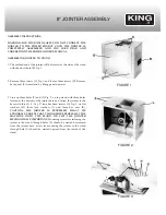
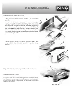
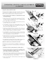
1. The outfeed end of the jointer will be located at the side of the stand
with the dust chute (B) Fig. 1.
2. Remove three screws (C) Fig. 1, and loosen three screws (D). Remove
back panel (E) from stand by lifting panel upward.
3. Line up three holes (F) and (L) Fig. 2, on top stand with three holes
located at the bottom of the jointer base and fasten the jointer to the
base with three 3/8 - 16 x 2
˝
long hex head screws (G) Fig. 3, six flat
washers (H), three lock washers (J), and three hex nuts (K).
CAUTION: THE JOINTER IS EXTREMELY HEAVY. WE
STRONGLY SUGGEST THAT TWO OR MORE PEOPLE LIFT THE
MACHINE ONTO THE STAND OR LIFT THE JOINTER
MECHANICALLY. IMPORTANT:
Mounting screws for fastening the
jointer to the stand through holes (F) should be started downward
from the jointer base. Screw for mounting the jointer to the stand
through hole (L) should be started upward from the inside of the
stand.
FIGURE 1
FIGURE 2
FIGURE 3

