ADJUSTING FENCE POSITIVE STOPS
The fence has been equipped with positive stops that allow you to
rapidly tilt the fence to the 90
0
and 45
0
angles, inward or outward, to the
table. To check and adjust the positive stops, proceed as follows:
1. MAKE CERTAIN THE MACHINE IS DISCONNECTED FROM
THE POWER SOURCE.
2. Position the fence at 90
0
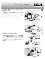
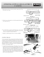
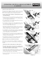
to the table. Make certain flip stop (F) Fig. 37,
is lowered as shown, and adjustment screw (H) is contacting the flip
stop (F); then tighten locking handle (D).
3. Place a square (K) Fig. 37, on the table and against the fence, as shown,
and check if the fence is 90
0
to the table.
4. If an adjustment is necessary, loosen locking handle (D) Fig. 37 and
lock nut (L). Rotate adjustment screw (F) until you are certain the
fence is 90
0
to the table. Tighten lock nut (L).
5. Rotate flip stop (F) Fig. 38, tilt fence outward as far as it will go and
tighten locking handle (D). Place a square (K) on the table and against
the fence to check if the fence is 45
0
outward to the table.
6. If an adjustment to the positive stop is necessary, loosen locking
handle (D) Fig. 38, and lock nut (M). Rotate adjustment screw (N) until
you are certain the fence is 45
0
outward the table.
7. Tilt the fence (G)
Fig. 39, inward as far as it will go and tighten locking
handle (D). Using a square (K) on the table and against the fence, check
if the fence is 45
0
inward to the table.
8. If an adjustment is necessary, loosen lock nut (P) Fig. 39. Rotate screw
(R) until you are certain the fence is 45
0
inward to the table.
REMOVING, REPLACING AND RESETTING KNIVES
If the knives are removed from the cutterhead for replacement or
regrinding, care must be used in removing, replacing and resetting them
as follows:
1.
DISCONNECT THE MACHINE FROM ITS POWER SOURCE.
2. Move the fence to the rear and remove the cutterhead guard.
WARNING: BE EXTREMELY CAREFUL THAT YOUR HANDS DO
NOT COME IN CONTACT WITH THE KNIVES.
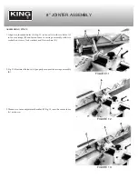
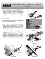
3. Using wrench (A) Fig. 40, slightly loosen the locking screws, three of
which are shown at (B) Fig. 40, in each knife slot by turning the screws
(B) clockwise. This relieves stress in the cutterhead.
4. Loosen screws (B) Fig. 40, further and remove knife (C)
Fig. 41, and
knife locking bar (D).
OPERATING CONTROLS AND ADJUSTMENTS
8” JOINTER
FIGURE 37
FIGURE 38
FIGURE 39
FIGURE 40

