


POWER SUPPLY
WARNING:
YOUR DUST COLLECTOR MUST BE CONNECTED TO A 120V, 15-AMP
CIRCUIT. FAILURE TO CONNECT IN THIS WAY CAN RESULT IN INJURY FROM
SHOCK OR FIRE.
GROUNDING
Your dust collector must be properly grounded. Not all outlets are properly grounded. If
you are not sure if your outlet is properly grounded, have it checked by a qualified
electrician.
WARNING:
IF NOT PROPERLY GROUNDED, THIS DUST COLLECTOR
CAN CAUSE ELECTRICAL SHOCK, PARTICULARLY WHEN USED IN DAMP
LOCATIONS. TO AVOID SHOCK OR FIRE, IF THE POWER CORD IS WORN OR
DAMAGED IN ANY WAY, HAVE IT REPLACED IMMEDIATELY.
If this dust collector should malfunction or breakdown, grounding provides a path of least
resistance for electric current, to reduce the risk of electric shock. It is equipped with a
cord having an equipment-grounding conductor and grounding plug. The plug must be
plugged into an appropriate outlet that is properly installed and grounded in accordance
with all local codes and ordinances. See Fig.1.
WARNING:
TO MAINTAIN PROPER GROUNDING, DO NOT REMOVE OR ALTER THE
GROUNDING PRONG IN ANY MANNER.
EXTENSION CORDS
The use of any extension cord will cause some loss of power. See Fig.2 below to
determine the minimum wire size (A.W.G-American Wire Gauge) extension cord. Use
only 3-wire extension cords which have 3-prong grounding type plugs and 3-hole
receptacles which accept the tool’s plug. For circuits that are further away from the
electrical circuit box, the wire size must be increased proportionately in order to deliver
ample voltage to the dust collector motor. Refer to Fig.2 for wire length and size.
SPECIFICATIONS &
ELECTRICAL INFORMATION
Technical Specifications
Model..........................................................................................................KC-1101C
Voltage................................................................................................................120V
Amperage ............................................................................................................5.7A
Cycle/Phase ........................................................................................60Hz, 1 phase
Air Suction....................................................................................................590 CFM
Inlet/Outlet Diameter................................................................................................4”
LENGTH OF
EXTENSION CORD
0-25 FEET
26-50 FEET
51-100 FEET
WIRE GAUGE REQUIRED
(AMERICAN WIRE GAUGE)
120V LINES
NO.16
NO.16
NO.14
Figure 2
Figure 1
PROPERLY GROUNDED
OUTLET
CURRENT
CARRYING
PRONGS
GROUNDING
PRONG
Installing Wheel Casters
This dust collector comes with 2 locking
caster wheels and 2 non-locking caster
wheels. Install both locking casters on the
same side. To install a wheel caster (A) Fig.3
to the the underside of the frame, make sure
caster wheel has a nut (B) threaded all the
way and a washer (C) placed on the caster
shaft. Insert caster shaft through the
underside of the frame and secure in place
using the acorn nut (D). Use 2 open end
wrenches to tighten securely. Repete for the
other 3 caster wheels.
Attaching Dust Collector Bag to outlet
Attach the collector bag (A) Fig.4 to the outlet
(B) with dust bag clamp (C), fix into place by
tightening screw (D) on dust bag clamp with a
flat head screwdriver.
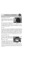
Turning Dust Collector On & Off
Note: Before connecting power cord to power
source, make sure that the switch is in the
“off” position.
The dust collector can be turned on by
flipping the switch (A) Fig.5 into the “on”
position. Flip to the “off” position to turn dust
collector off. There is a removable safety key
(B) in the tip of the switch that can be
removed when in the “off” position. When the
key has been removed the dust collector
can’t be used.
This dust collector comes with a circuit
breaker reset button (C) Fig.5, if the motor
overloads, the circuit breaker will be tripped
and the motor will stop. Turn the switch to the
“off” position and let the motor cool down for
15 minutes. Press the reset button and restart
the motor.
ASSEMBLY & OPERATION
Figure 3
Figure 4
Figure 5


