OPERATION,
MAINTENANCE & STORAGE
OPERATING PROCEDURES
Preparation for use:
1) Before attaching air hose or any accessory, make sure the pressure switch lever is set to “OFF” and the pressure regulator is closed.
2) Install air hose male coupler into the female quick connect (C) Fig.5 on the air compressor, to do this, push quick connect collar backwards
and hold it in this position. Push male coupler all the way into female quick connect and release collar to secure male coupler.
3) Turn the pressure switch lever to “ON/AUTO” (A) Fig.11 and allow tank pressure to build. Motor will stop when tank pressure reaches “cut-out”.
4) Open the pressure regulator (D) Fig.6 by turning it clockwise. Adjust the pressure regulator to the correct pressure setting (do not exceed the
maximum rating of the tool being used). Observe outlet air pressure on outlet pressure gauge (E) Fig.6 as reference. The compressor is ready for use.
After Use:
5) Set the “OFF/AUTO” lever to “OFF”.
6) Turn the pressure regulator counterclockwise to set the outlet pressure to zero.
7) Disconnect air hose.
8) Pull ring on safety valve (C) Fig. 6, allowing air to bleed from the tank until tank pressure is approximately 20 PSI. Release safety valve ring.
9) Drain water from air tank. Turn drain valve (A) Fig.10, turn it counterclockwise to open.
WARNING!
: Water will condense in the air tank. If not drained water will corrode and weaken the air tank causing a risk of air tank rupture.
NOTE:
If drain valve is plugged, pull ring on safety valve (C) Fig.6, and hold until air pressure has been released. The valve can then be removed,
cleaned, and reinstalled.
10) After the water has been completely drained, turn drain valve clockwise to close. The air compressor can now be stored.
MAINTENANCE
Before doing any maintenance or adjustments to your air compressor, the following safety precautions should be taken:
- Disconnect electrical power, drain air tank of pressure.
Daily or before each use
1) Check oil level. Oil level must be in the centre of the red dot of oil sight glass.
2) Drain condensation from tank.
3) Check for any unusual noise or vibration.
4) Be sure all nuts and bolts are tight.
Monthly
1) Inspect air system for leaks by applying soapy water to all joints. Tighten those joints if leakage
is observed.
250 hours or six months (whichever comes first)
1) Change compressor oil. See following instructions
2) Replace oil more often if used near paint spraying operations or in dusty environments.
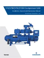
CHANGING OIL
To change oil, oil must be drained from the crank case by removing oil sight glass (C) Fig.12. Drain oil and replace oil sight glass. To fill the crank
case with oil, first unscrew and remove oil breather cap (A), pour air compressor oil (SAE30 weight non-detergent oil) into crankcase oil opening
(B) until the oil level reaches the red dot at the centre of the oil sight glass (C). Replace oil breather cap (A).
KEEP TOOL CLEAN
Periodically blow out all air passages with dry compressed air. Clean all plastic parts with a soft damp cloth. NEVER use solvents to clean
plastic parts. They could possibly dissolve or otherwise damage the material.
CAUTION
: Wear safety glasses while using compressed air.
FAILURE TO START
Should your compressor fail to start, check to make sure the prongs on the cord plug are making good contact in the outlet. Also, check for blown
fuses or open circuit breakers in the line.
STORAGE
1) Set the “OFF/AUTO” lever to “OFF”.
2. Turn the regulator counterclockwise to set the outlet pressure to zero.
3. Remove the air hose.
4. Pull ring on safety valve (C) Fig.6, allowing air to bleed from the tank, until tank pressure is approximately 20PSI. Release safety valve ring.
5. Drain water from air tank. Turn drain valve (B) Fig.7, counterclockwise, to open. NOTE: If drain valve is plugged, pull ring on safety valve (C)
Fig. 6, and hold until air pressure has been released. The valve can then be removed, cleaned, and reinstalled.
6. After the water has been completely drained, turn drain valve to close. The air compressor can now be stored.
FIGURE 12