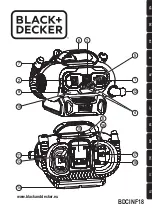
SPECIFICATIONS & ELECTRICAL INFORMATION
WARNING
ALL ELECTRICAL CONNECTIONS MUST BE DONE BY A QUALIFIED ELECTRICIAN. FAILURE TO COMPLY MAY RESULT IN SERIOUS
INJURY! ALL ADJUSTMENTS OR REPAIRS MUST BE DONE WITH THE COMPRESSOR DISCONNECTED FROM THE POWER SOURCE.
FAILURE TO COMPLY MAY RESULT IN SERIOUS INJURY!
POWER SUPPLY
WARNING:
YOUR COMPRESSOR MUST BE CONNECTED TO A 120V
OUTLET, USING A 15-AMP TIME DELAY FUSE OR CIRCUIT BREAKER.
FAILURE TO CONNECT IN THIS WAY CAN RESULT IN INJURY FROM
SHOCK OR FIRE.
GROUNDING
Your compressor must be properly grounded. Not all outlets are properly
grounded. If you are not sure if your outlet is properly grounded, have it
checked by a qualified electrician.
WARNING:
IF NOT PROPERLY GROUNDED, THIS COMPRESSOR CAN
CAUSE ELECTRICAL SHOCK, PARTICULARLY WHEN USED IN DAMP
LOCATIONS. TO AVOID SHOCK OR FIRE, IF THE POWER CORD IS WORN
OR DAMAGED IN ANY WAY, HAVE IT REPLACED IMMEDIATELY.
If this compressor should malfunction or breakdown, grounding provides
a path of least resistance for electric current, to reduce the risk of electric
shock. This compressor is equipped with a cord having an equipment-
grounding conductor and grounding plug. The plug must be plugged into
an appropriate outlet that is properly installed and grounded in accordance
with all local codes and ordinances.
WARNING:
TO MAINTAIN PROPER GROUNDING, DO NOT REMOVE OR
ALTER THE GROUNDING PRONG IN ANY MANNER.
120V OPERATION
As received from the factory, your compressor is ready to run for 120V
operation. This machine is intended for use on a circuit that has an outlet
and a plug which looks like the one illustrated in Fig.1.
WARNING:
DO NOT USE A TWO-PRONG ADAPTOR FOR THEY ARE NOT
IN ACCORDANCE WITH LOCAL CODES AND ORDINANCES. NEVER USE
IN CANADA.
FIGURE 1
LENGTH OF
CONDUCTOR
0-25 FEET
26-50 FEET
51-100 FEET
WIRE SIZES REQUIRED
(AMERICAN WIRE GAUGE)
120V LINES
NO.16
NO.16
NO. 14
FIGURE 2
EXTENSION CORDS
The use of any extension cord will cause some loss of power. IT
IS RECOMMENDED TO USE A LONGER AIR HOSE INSTEAD
OF AN ExTENSION CORD. Use the chart below in Fig.2 to
determine the recommended minimum wire size (A.W.G-
American Wire Gauge) extension cord. Use only 3-wire extension
cords which have 3-prong grounding type plugs and 3-hole
receptacles which accept the tool’s plug.
For circuits that are further away from the electrical circuit box, the
wire size must be increased proportionately in order to deliver
ample voltage to the motor. Refer to Fig.2 for wire length and size.
PROPERLY GROUNDED OUTLET
CURRENT CARRYING PRONGS
GROUNDING PRONG
SPECIFICATIONS
Model ..............................................................................................................................................................................................8438
Voltage ............................................................................................................................................................................................120V
Amperage ........................................................................................................................................................................................2.5A
RPM (no load speed) ......................................................................................................................................................................4,500
Phase ....................................................................................................................................................................................................1
Hertz................................................................................................................................................................................................60Hz
Maximum operating pressure ....................................................................................................................................................100 PSI
CFM @ 40 PSI ....................................................................................................................................................................................1.0
CFM @ 90 PSI ..................................................................................................................................................................................0.60
Tank size ............................................................................................................................................................................3 US Gallons