Kimray DUMP Скачать руководство пользователя страница 4

www.kimray.com

OIL & WATER VALVES

Installation, Operation & Maintenance Guide

4

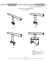
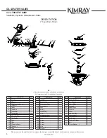
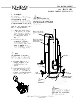
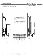
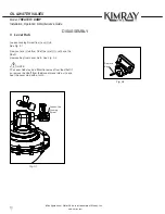
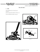
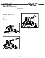
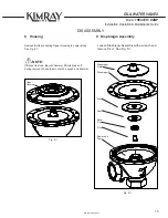
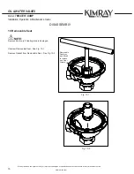
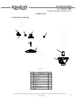
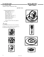
Model: TREATER / DUMP

ǂ

Configuration of Water Valve is a trademark of Kimray, Inc.


WARNING:


DO NOT exceed the maximum pressure specified on the 

nameplate.  Under no circumstances should the regulator 

supply pressure ever exceed the maximum psig.

  A4 Maintenance

Maintenance should be performed on a regular basis.  

Initial intervals of 12 months is recommended.  The 

maintenance interval may increase or decrease 

depending on changing application environments.  The 

valve can be repaired without being removed from the 

piPing.

Related Publications

The following publications are applicable for the regulator

Number Type 


         Title

Catalog Pages D:10.1-5

Abbreviations / Acronyms

The abbreviations that follow are used in this manual.

Term


Definition

SWA 


Screwed, Water, Angle

FWA 


Flanged, Water, Angle

Commonly Replaced Parts

•   Trim Set

•   Diaphragm

•   O-Ring

Occasional Replacement Parts

•   Body 


A5  Changes and Updates

A  Before you start

CAUTION:


The instructions provided herein should be completely 

reviewed and understood before operating or reparing this 

equipment.  All CAUTION and WARNING notes must be 

strickly observed to prevent personal injury or equipment 

damage.

  A1 Scope

NOTE:

Do not install, operate, or maintain a treater valve 

without being fully trained and qualified with the Kimray 

installation, operation and maintenance manual.  

To avoid personal injury or property damage, it is 

important to carefully read, understand, and follow all the 

contents of this manual, including all safety cautions and 

warnings.

If you have any  questions about this manual, contact 

your Kimray applications support group before proceed-

ing.

  A2 Introduction

This repair manual contains information for the SWA and 

FWA treater valves.

  A3 Description

The Kimray treater valve is designed as an oil or water 

valve for emulsion treaters, water knockouts and 

gunbarrels.  The treater valve is ideal for salt water 

disposal syStems.

CAUTION:


When ordered, the treater valve Configuration and 

construction materials were selected to meet specific 

pressure, temperature, pressure drop and fluid conditions.  

Since some Body / trim material combinations are limited 

in their pressure drop and temperature ranges, do not 

subject the pressure regulator to any other conditions 

without first contacting the Kimray Inc, sales office or a 

sales / applications representative.

Содержание DUMP

Страница 1: ...TREATERVALVE...

Страница 2: ...t to be construed as warranties for guarantees express or implied regarding Kimray products or services described herein or their use or application All sales are governed by our terms and conditions...

Страница 3: ...allation 7 DISASSEMBLY 2 Weight Drip Pot 9 3 Lever Hub 10 4 Shaft 11 5 Bonnet 13 6 Trunnion Hub 14 7 Stem Assembly 14 8 Housing 15 9 Diaphragm Assembly 15 10 Removable Seat 16 INSPECTION 11 Inspection...

Страница 4: ...paring this equipment All CAUTION and WARNING notes must be strickly observed to prevent personal injury or equipment damage A1 Scope NOTE Do not install operate or maintain a treater valve without be...

Страница 5: ...to modify or improve the special tools and equipment designs or specifications at anytime without notice SPECIAL TOOLS AND EQUIPMENT A6 Tip Kimray recommends using the above special tools and equipme...

Страница 6: ...4 16 17 27 2 3 12 4 13 14 15 5 25 24 19 21 23 36 29 22 20 18 Item Description Qty 1 Weight 1 2 Bonnet 1 3 Diaphragm Housing 1 4 Drip Pot 1 5 Body 1 6 Hex Bolt 1 7 Lever Bar 1 8 Lever Hub 1 9 Packing R...

Страница 7: ...t Do not share this line with any other equipment 4 Adjust weight on Lever Arm All the way out towards the end of lever bar will achieve 4 ft of liquid head All the way in towards Hub Assembly will ac...

Страница 8: ...ever Bar allowing the maximum 12 feet of liquid head Table 1 Lengths and Weights Size Standard Lever Bar Hi Head Lever Bar Weight Part No s 2 419 419L 424 3 420 420L 425 4 420 420L 426 6 420 420L 426...

Страница 9: ...weight by loosening the Bolt Unscrew Drip Pot from Nipple and remove Bleed Valve from Drip Pot See Fig 2 1 Remove both Bolts from the Lever Hub and remove Lever See Fig 2 2 2 Weight Drip Pot Bleed Va...

Страница 10: ...g 3 1 Remove Lever Hub from Shaft be careful to not bend the Shaft Remove Key from Lever Hub See Fig 3 2 NOTE The Lever Hub may be difficult to remove from the Shaft if so remove the Shaft from the Bo...

Страница 11: ...Recommended spare parts and stocked as repair kits Fig 4 1 Use an adjustable wrench to remove the Nut See Fig 4 1 Remove Packing Follower behind Nut See Fig 4 2 Remove Stuffing Box Assembly See Fig 4...

Страница 12: ...DUMP DISASSEMBLY Use a wrench to remove the Plug Remove Gasket from Plug See Fig 4 4 Use large punch and carefully tap Shaft out See Fig 4 5 NOTE If Shaft is bent it may be necessary to cut the Shaft...

Страница 13: ...UMP DISASSEMBLY Kimray reserves the right to modify or improve the designs or specifications of such products at any time without notice 5 Bonnet Remove 4 Bolts from Bonnet and remove Bonnet See Fig 5...

Страница 14: ...Stem Assembly from Body See Fig 7 1 Pull Pin from Stem Assembly Pull Stem through Diaphragm Bolt Remove Diaphragm Remove Retainer from Diaphragm Bolt See Fig 7 2 Pin Diaphragm Retainer Diaphragm Bolt...

Страница 15: ...ammer if Bolts break off during removal knock them out with a punch and hammer Diaphragm Plate Diaphragm Disc Seat Ratio Plug Pivot Removable Seat Upper Housing 9 Diaphragm Assembly Loosen Diaphragm A...

Страница 16: ...ify or improve the designs or specifications of such products at any time without notice DISASSEMBLY 10 Removable Seat NOTE Remove Seat only if Seating area is damaged Removable Seat may be difficult...

Страница 17: ...ght to modify or improve the designs or specifications of such products at any time without notice Item Description Qty 1 Lever Hub 1 2 Nut 1 3 Stuffing Box 1 4 Bonnet 1 5 Plug 1 6 Stem 1 7 Housing 1...

Страница 18: ...g 11 4 Stem See Fig 11 5 Diaphragm Plate See Fig 11 6 Ratio Plug See Fig 11 7 Removable Seat See Fig 11 8 Housing See Fig 11 9 Body See Fig 11 10 Use an air nozzle to blow out the particles from insid...

Страница 19: ...OIL WATER VALVES Installation Operation Maintenance Guide 19 www kimray com Model TREATER DUMP INSPECTION Fig 11 8 Fig 11 9 Fig 11 10...

Страница 20: ...the Body as shown See Fig 12 1 Flip Removable Seat upside down and apply all purpose grease See Fig 12 2 Install Removable Seat in Body may have to use Seat Wrench See Fig 12 3 12 4 CAUTION Over tight...

Страница 21: ...rew driver to work the Rubber Seat into place Insert Pivot into Ratio Plug Insert into Seat Insert into Disc Insert into Diaphragm Insert into Diaphragm plate See Fig 13 1 Diaphragm Plate Diaphragm Di...

Страница 22: ...Guide 22 Model TREATER DUMP ASSEMBLY 14 Housing Place Diaphragm Housing on Body See Fig 14 1 14 2 NOTE Make sure you tighten the Bolts in a criss cross pattern to avoid any miss alignment For 2in 3in...

Страница 23: ...NOTE DO NOT DROP Stem Assembly into Housing Install Stem Diaphragm Assembly into Diaphragm Plate See Fig 15 2 Install Stem Pin through small hole in Stem Stem Hand start brass Diaphragm Bolt into Diap...

Страница 24: ...t over Stem Assembly and onto Stem Diaphragm Assembly See Fig 16 1 Fig 16 2 shows correct orientation of Bonnet to Body NOTE Make sure you tighten the Bolts in a criss cross pattern to avoid any miss...

Страница 25: ...large diameter of Shaft Line up Key with the Keyway inside the Link Hub and slide Shaft and Key into Hub Long end of Shaft will be oriented opposite the pressure port of the Diaphragm Housing NOTE Us...

Страница 26: ...rque 19 Lever Hub Install the Washer onto the Shaft Install the Gasket onto the Shaft Install the Stuffing Box onto the Shaft Install the Packing Ring onto the Shaft Install the Teflon Packing onto th...

Страница 27: ...ntenance Guide 27 www kimray com Model TREATER DUMP ASSEMBLY Line up Keyway on Shaft and Lever Hub Lightly tap Key into Keyway NOTE When completed the Key the end of the Shaft and the side of the Leve...

Страница 28: ...ure port three full turns Thread the Bleed Valve Body into the end pressure port of the Drip Pot Body Apply Primer and Blue Loctite HERE Apply Primer and Blue Loctite HERE 21 Serial Tag Lightly tap Dr...

Страница 29: ...pply air off and make sure the Gauge is holding pressure on the upstream side If Gauge falls off then you have leakage Check if any leakage is coming out the downstream side Spray soaped water on Hous...

Страница 30: ...www kimray com OIL WATER VALVES Installation Operation Maintenance Guide 30 Model TREATER DUMP Page left blank...

Страница 31: ...001 certified manufacturer Kimray quality assurance process maintains strict controls of materials and the certification of parts used in Kimray HPCV Please visit our website for up to date product da...

Страница 32: ...2015 Kimray Inc 1 18 MKSLLS RM0004 Kimray com...

Отзывы: