August 1999
76-100016-001
Intelligent Suppression Control/Fire Alarm System
PEGAsys
7-3
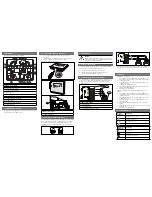
Figure 7-5. Installation for Multi-Loop
Table 7-1 RX/TX Configuration Selection
r
e
p
m
u
J
4
e
l
y
t
S
6
e
l
y
t
S
6
e
l
y
t
S
p
o
o
L
/
W
r
o
t
a
l
o
s
I
7
e
l
y
t
S
2
W
&
1
W
n
e
p
O
d
e
t
r
o
h
S
d
e
t
r
o
h
S
d
e
t
r
o
h
S
2
P
J
d
e
t
r
o
h
S
d
e
t
r
o
h
S
n
e
p
O
n
e
p
O
3
P
J
d
e
t
r
o
h
S
d
e
t
r
o
h
S
n
e
p
O
n
e
p
O
NOTE:
Style seven (7) requires the use of loop isolators, the
RX/TX module requires the use of one (1) P/N 74-
200012-001 isolator module to operate in the Style 7
configuration.
a.
Remove RX/TX module from packing and inspect for physi-
cal damage.
b.
Ensure jumper configuration is set. Refer to Table 7-1 set-
ting per wiring style used.
c.
Install loop isolator, P/N 74-200012-001, if used.
d.
Connect 24VDC wiring from terminal block (TB1-TB8) to
24VDC input plug J1. The terminal block which will be used
to power the RX/TX will be dependant upon which slot the
RX/TX will be installed into.
e.
Install the short 6 conductor cable from the RS-232 port on
the RX/TX to either RJ12 sockets JP1-JP8. The socket se-
lected is dependant upon which slot the RX/TX will be in-
stalled into.
f.
Place the RX/TX against the mounting bracket, in the
PE-
GAsys
, over the desired slot to be placed in. Install the two
mounting screws and tighten until snug.
g.
Removal of the RX/TX would be in the reverse order.
NOTE:
Since the RX/TX's are not addressed by switches the
slot that they are installed in will become there address.
Example: A RX/TX installed in JP1 on the multi-loop
motherboard will become RX/TX 1, Loop 1. If the same
RX/TX was changed into JP4, the address would
become RX/TX 4, Loop 4.
7-7
INSTALLATION OF I/O MODULES
The I/O modules can be inserted into the motherboard in any
order. The CCM automatically reads the I/O modules type and
address upon registration. However, it is recommended that you
insert modules performing like functions adjacent to each other
to facilitate identification and field wiring runs. After powering
up the system, you can request a list of I/O Module assign-
ments from the system menu to verify their registration and ac-
curacy of module address(s).
CAUTION
All personnel installing or servicing
PEGAsys
equip-
ment must wear a grounding strap when working
in the Central Control panel to avoid generating
static electricity which can destroy integrated cir-
cuits. Input / Output Module printed circuit boards
are shipped in anti-static plastic bags and should
be kept in these bags until you are ready to install
them. When you remove these circuit boards from
the Motherboard, they should be replaced in to the
appropriate bags. NEVER PACK THESE BOARDS
IN STYROFOAM OR PLASTIC PELLETS.
WARNING
Input/Output Modules should never be installed in
a “powered-up” system. Always disconnect both
AC and battery power before installing or remov-
ing I/O Modules.
To remove a I/O module from the system; secure power, re-
move terminal block from module, remove the two mounting
screws and pull out the module.
The following paragraphs describe the installation procedure
for each available I/O module type.
7-7.1
Signal Audible Output Module
The following paragraph provides the step-by-step procedure to
install a signal audible output module into the
PEGAsys
system.
a.
Remove the signal audible output module from packing and
inspect for physical damage.
b.
Set address switches. Refer to drawing 06-235371-006 in
Appendix I for address switch settings.
c.
Set jumpers W1-W3 for appropriate Y/Z wiring styles (refer
to Drawing No. 06-235443-006 in the back of the manual
for jumper settings).
d.
Cut jumper between W9 & W10 if using an auxiliary 24VDC
power input.
e.
Install module onto the motherboard. Ensure the connec-
tor mates properly.
f.
Insert and tighten mounting screws. Refer to appropriate
Figure 5-1 or 5-2.
Содержание PEGAsys
Страница 2: ......
Страница 4: ......
Страница 6: ...ii THIS PAGE IS INTENTIONALLY LEFT BLANK ...
Страница 16: ......
Страница 154: ...220423 KIDDE FENWAL Inc 400 Main Street Ashland MA 01721 Attn Documentation Manager Place Stamp Here FOLD FOLD ...
Страница 155: ......


