INSPECT CHARGING SYSTEM
VOLTAGE DROP TEST OF ALTERNATOR OUTPUT WIRE
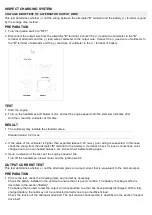
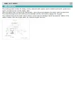
This test determines whether or not the wiring between the alternator "B" terminal and the battery (+) terminal is good
by the voltage drop method.
PREPARATION
1. Turn the ignition switch to "OFF".
2. Disconnect the output wire from the alternator "B" terminal. Connect the (+) lead wire of ammeter to the "B"
terminal of alternator and the (-) lead wire of ammeter to the output wire. Connect the (+) lead wire of voltmeter to
the "B" terminal of alternator and the (-) lead wire of voltmeter to the (+) terminal of battery.
TEST
1. Start the engine.
2. Turn on the headlamps and blower motor, and set the engine speed until the ammeter indicates 20A.
And then, read the voltmeter at this time.
RESULT
1. The voltmeter may indicate the standard value.
Standard value: 0.2V max
2. If the value of the voltmeter is higher than expected (above 0.2V max.), poor wiring is suspected. In this case
check the wiring from the alternator "B" terminal to the battery (+) terminal. Check for loose connections, color
change due to an over-heated harness, etc. Correct them before testing again.
3. Upon completion of the test, set the engine speed at idle.
Turn off the headlamps, blower motor and the ignition switch.
OUTPUT CURRENT TEST
This test determines whether or not the alternator gives an output current that is equivalent to the normal output.
PREPARATION
1. Prior to the test, check the following items and correct as necessary.
Check the battery installed in the vehicle to ensure that it is good condition. The battery checking method is
described in the section "Battery".
The battery that is used to test the output current should be one that has been partially discharged. With a fully
charged battery, the test may not be conducted correctly due to an insufficient load.
Check the tension of the alternator drive belt. The belt tension check method is described in the section "Inspect
drive belt".
Содержание Carnival 2009
Страница 1: ...Engine Electrical System General Information Engine SLJ YPcal System ...
Страница 13: ...Engine Electrical System Ignition System Engine Electrical System ...
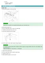
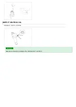
Страница 18: ...INSPECT IGNITION COIL 1 Standard 0 0715 0 015 Mesure the resistance between the terminals No 1 and No 3 ...
Страница 19: ...Engine Electrical System Charging System Engine SLJ YPcal System ...
Страница 26: ...Engine Electrical System Charging System Alternator Engine SLJ YPcal System ...
Страница 27: ...2009 G 2 7 DOHC COMPONENT ...
Страница 31: ...Engine Electrical System Charging System Battery Engine SLJ YPcal System ...
Страница 36: ...Engine Electrical System Starting System Engine SLJ YPcal System ...
Страница 40: ...Engine Electrical System Starting System Starter Engine SLJ YPcal System ...
Страница 41: ...2009 G 2 7 DOHC COMPONENT ...
Страница 48: ...Engine Electrical System Starting System Starter Relay Engine Electrical System ...


