

InTandem
®
Table System - Leg-Mounted CPU Holder
Assembly Instructions
Assemble units as described herein only. To do otherwise
may result in instability. All screws, nuts and bolts must be
tightened securely and must be checked periodically after
assembly. Failure to assemble properly, or to secure parts
may result in assembly failure and personal injury.
1330 Bellevue Street • P.O. Box 8100 • Green Bay, WI 54308-8100 • Tel 1-800-424-2432 • www.ki.com
© 2012 KI All Rights Reserved • Litho in USA • Code KI-62368/KI/PDF/1212
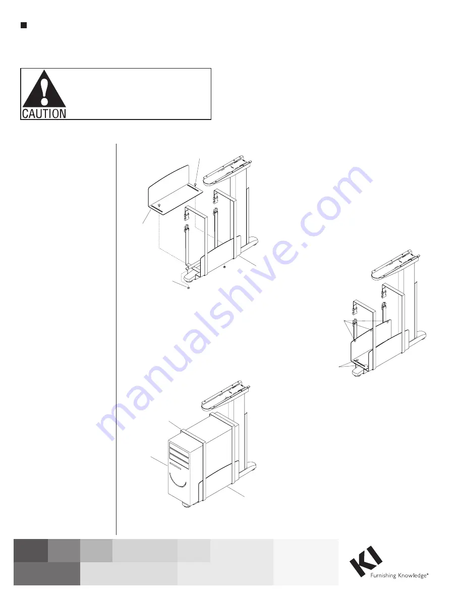
3. If not installed already, attach leg
to worksurface and carefully turn
desk assembly to the upright
position. Insert ¼ x ½” carriage
bolt into large slot in CPU holder
side and align bolt with hole in
CPU holder base. Thread ¼”
nut onto carriage bolt, leaving
slightly loose until adjustment for
CPU size is completed. Repeat
assembly for second carriage bolt
and nut (Figure 3).
4. Determine location of ½” diameter
self-adhesive bumpers and place
accordingly. The rubber bumpers
should be spaced equally on the
horizontal surface of the CPU
holder side while the felt bumpers
should be placed near the top
edge of both the CPU holder base
and CPU holder side (Figure 4).
5. Set CPU in place and adjust
CPU holder side appropriately.
Tighten both ¼” nuts. Snap CPU
securing strap male and female
ends together and pull strap end
tight until CPU is held securely
(Figure 5).
3. If not installed already, attach leg to
worksurface and carefully turn desk
assembly to the upright position. Insert
¼ x ½” carriage bolt into large slot in
CPU holder side and align bolt with
hole in CPU holder base. Thread ¼”
nut onto carriage bolt, leaving slightly
loose until adjustment for CPU size is
completed. Repeat assembly for
second carriage bolt and nut
(Figure 3).
4. Determine location of ½ diameter
self-adhesive bumpers and place
accordingly. The rubber bumpers
should be spaced equally on the
horizontal surface of the CPU Holder
Side while the felt bumpers should be
placed near the top edge of both the
CPU Holder Base and CPU Holder Side
(Figure 4).
5. Set CPU in place and adjust CPU
holder side appropriately. Tighten both
¼” nuts. Snap CPU securing strap
male and female ends together and pull
strap end tight until CPU is held
securely (Figure 5).
InTandem Leg CPU Holder
Figure 3
Figure 4
Figure 5
1
/ x ½”
carriage bolt
4
CPU
holder side
CPU
holder base
CPU
holder base
CPU
securing strap
1
/ ” nut
4
½” self adhesive
rubber bumpers
CPU
½” self adhesive
felt bumpers


