22
Backrest Assembly
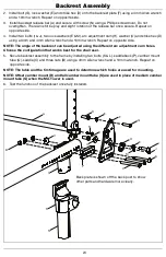
NOTE: Remove any cushion or seating components that may be in the way when removing current
backrest. Remove the current backrest and back posts before beginning.
Locking Fold Down Back
NOTE: The new Locking Fold Down Back assembly, standard and transit, uses new backrest tubes.
If the chair does not already have the new backrest design, new backrest tubes are needed as the
old tubes are not compatible.
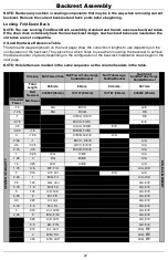
CG and Hardware Reference Table
The table and diagram (shown on the next page) show the correct bolt lengths to use depending on the
configuration of the backrest. They also show which holes to use when mounting the backrest to achieve
the desired center of gravity depending on the configuration of the backrest. Installation steps begin on the
next page.
NOTE: Hole letters are marked in the same sequence as the column headers in the table.
Stackup Nut/Tower/Tube Nut/Tower/Tube/Large
Saddle/Bracket
Nut/Tube/Large
Saddle/Bracket
Nut/Small
Saddle/Tube/Large
Saddle/Bracket
Total
Length
55.5mm
65mm
50.5mm
53.7mm
Bolt
Needed
003232 (55mm)
101127 (65mm)
101781 (50mm)
003232 (55mm)
Standard
Tower
MX-Tower
C
E
N
T
E
R
O
F
G
R
A
V
IT
Y
-1.5
A/A
E/C/A
G/E
H
O
LE
A
LIG
N
M
E
N
T
-1.25
B/A
F/C/B
F/E
-1
C/B/A, G/D/C
F/E
-0.75
B/A/A, F/C/C
E/E
-0.5
A/A/A, G/D/D
E/E
-0.25
-1.5
B/B/B, F/D/D
0
-1.25
A/B/B, G/E/E
A/A
0.25
-1
B/C/C, F/E/E
A/A
0.5
-0.75
A/C/C, E/E/E
A/A
0.75
-0.5
B/D/D, D/E/E
A/A
1
-0.25
G/G
C/E/E
A/A
1.25
0
F/G
B/E/E
A/A
1.5
0.25
G/H
A/E/E
A/A
1.75
0.5
B/F, F/H
A/A, D/D
2
0.75
A/F, G/I
D/D
A/A
2.25
1
B/G, F/I
A/A, D/D
2.5
1.25
A/G, G/J
A/A, E/E
2.75
1.5
B/H, F/J
A/A, E/E
3
1.75
A/H, G/K
A/A, E/E
3.25
2
B/I, F/K
A/A, E/E
3.5
2.25
A/I, G/L
A/A, E/E
3.75
2.5
B/J, F/L
A/A, E/E
4
2.75
A/J, G/M
A/A, E/E
4.25
3
B/K, F/M
A/A, E/E
3.25
A/K, G/N
A/A, E/E
3.5
B/L, F/N
A/A, E/E
3.75
A/L, G/O
A/A, E/E
4
B/M, F/O
A/A, E/E
4.25
A/M, G/P
A/A, E/E

