background image

Balancing

Technical Note: 

Design with VAV/Constant Flow Boxes and Ducted Applications

In applications where the fan filter units will be ducted with upstream VAV, constant flow boxes, valves, or other airflow 

devices that may have varying airflows, or modes, a constant flow program is not recommended.
In systems where two controllers are trying to compensate to adjust to a constant airflow, the system will be unable to 

stabilize. This results in constant adjustment of both controllers until the Krown Fan Filter Unit motor shuts off. The ECM 

with constant torque motor program or PSC motor is suggested for this type of application.

The Krown Fan Filter Unit is designed to overcome the pressure drop of the filter only. The motor is not intended to pull air 

down supply ductwork, nor to experience a positive static pressure at the inlet forcing air through the fan. Krown Fan filter 

units should be installed in a system where the inlet static will be neutral or slightly negative.
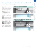
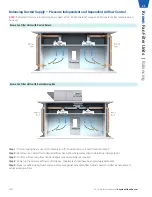
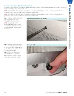
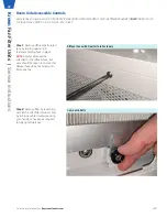
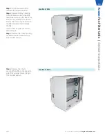
In ducted applications, it is critical that primary air be balanced prior to installing the Krown Fan Filter unit. The primary air 

controls should be locked in position post balancing, and the is installed and running. Similarly, the Krown Fan Filter series 

should be bench-set by using a flow hood and adjusting the speed controller, as required, to the same balanced, primary 

airflow rate before the is mated with the duct. Alternatively, the Technical Note: Design with VAV/Constant Flow Boxes and 

Ducted Applications can also be followedl.
To prevent a high static pressure build up at the Krown Fan Filter series during start up, the Krown Fan Filter unit should be 

energized prior to the system. This helps to prevent the possibility of backwards rotations of the blower wheel, which will 

eventually lead to the motor shutting off.

For any additional information, or troubleshooting assistance on systems and design with Krown fan filter units 


used in sequence with a variable upstream air source, contact contact Keystone Clean Air Solutions help at  

[email protected], or dial (470)-604-9938.

For more information visit 

KeystoneCleanAir.com

v001

21

Kr

own 

Fan Filter Units | 

Balancing

Содержание Krown

Страница 1: ...Krown Fan Filter Units v001 Issue Date 02 23 22 2022 Keystone Clean Air Solutions All rights reserved INSTALLATION SERVICE MANUAL...

Страница 2: ...pply Units 22 Balancing Ducted Supply Pressure Independent and Dependent Airflow Control 23 Balancing Ducted Supply Pressure Independent and Dependent Airflow Control 25 Service Instructions Pre Filte...
Страница 3: ...the shipping company and file a freight claim Filter Information Ensure that all HEPA ULPA filters are stored in a clean dry location in a vertical position as labeled on the carton Do not open the H...

Страница 4: ...e four 4 stickers located on the back of the plenum For ease of troubleshooting assistance replacement parts and general factory assistance it is recommended that the order number and model line strin...

Страница 5: ...tring for Bench Top Replaceable filter Krown X X I SUPPLY 24 48 BTR HEPA FC ECM 115 CF TMB ECMSC TC DSW 115 ASSP WPF PL AL F EM PL WM F EM Step 3 Raise the unit through the ceiling grid at an angle un...

Страница 6: ...ontroller Step 2 Wire speed controller according to wiring diagram Wall mounted speed controller will be wired in series with the motor Step 3 Attach the wall mounted controls faceplate to the electri...

Страница 7: ...analog voltage signal from BAS others or Price WMSC please remove ECMSC from control box Connect 0 10VDC COMMON to BAS SIGNAL BAS COMMON on back of ECMSC make sure to feed wires through grommet on co...

Страница 8: ...311 373 95 140 VDC CFM 19 207 VDC CFM 47 174 VDC CFM 70 197 VDC CFM 79 167 VDC CFM 138 212 VDC CFM 81 190 Supply Constant Torque Backward Curve Velocity 24x36 24x48 FPM BTR BC RSR BC BTR BC RSR BC 45...

Страница 9: ...put BAS Voltage Response Notes 0 1 VDC Local control mode using push buttons Local setpoint can be adjusted from 0 100 using push buttons 1 2 VDC Motor Off Recommended sending a 1 5 VDC signal to comm...

Страница 10: ...et Sample line string Krown X X I SUPPLY 24 48 RSR HEPA FC ECM 115 CF R TMB BACnet BFC TC DSW 115 PC 115 ASSP WPF PL AL F AL PL B12 F B12 Step 4 If the unit has an RSR filter install the filter now re...

Страница 11: ...box The service tool connects to the RJ12 port on the BFC board to allow full control up to 6 feet away from the control panel Sample line string KrownCS X X I ECM BFC BFC ST 250002 600 For more infor...

Страница 12: ...ECM CFM 5 08 44 ECM CFM 4 45 32 ECM CFM 6 93 42 ECM CFM 5 50 41 Supply Constant Torque Forward Curve Velocity 24x24 24x36 24x48 FPM BTR FC RSR FC BTR FC RSR FC BTR FC RSR FC 45 95 ECM CFM 10 82 12 ECM...

Страница 13: ...quations are based on a 1 5 Volt scale The BAS input voltage is a 2 10 VDC scale and therefore VDC calculated for a given CFM using the equations must be doubled to achieve that CFM using the BAS inpu...

Страница 14: ...gaurd Room Side Replaceable Filter RSR Quick Start Guide RSR BTR Bench Top Replaceable Filter BTR Sample line string Krown X X I 24 48 BTR FC ECM 115 10 CF HEPA BFC DSW 115 PC 115 TMB ASSP FL ML BACne...

Страница 15: ...if the LED indicator option has been selected one port will be used for the LED installation ASSP on BTR unit ASSP INJ RSR unit Optional Aerosol Injection Port INJ Sample line string Krown X X I SUPPL...

Страница 16: ...r Step 3 Remove threaded standoff and lock washer from LED cable assembly Step 4 Thread cable through static pressure port on face of BTR filter NOTE It is recommended to rest the filter frame on 2x4...

Страница 17: ...nstallation section of this manual Step 8 Refer to wiring diagram located in control box to connect LED leads to terminal block NOTE If unit has BFC speed controller LED leads will need to be connecte...

Страница 18: ...r operation when the static pressure is above 0 1 w g Red Troubleshoot Motor Indicates motor is not in operation and that unit static pressure is below 0 1 w g Calibration Filter LED will come factory...

Страница 19: ...user diffuser face must be removed to access Step 5 Using an obstruction piece of cardboard or equivalent slowly increasing pressure on the unit by blocking off more and more of the diffuser face unti...

Страница 20: ...lean filter pressure Red Off Adjust setpoint check control mode Indicates motor setpoint is 0 If alternate setpoint is expected please check control mode Blinking Red Low Pressure Troubleshoot motor I...

Страница 21: ...ducted applications it is critical that primary air be balanced prior to installing the Krown Fan Filter unit The primary air controls should be locked in position post balancing and the is installed...

Страница 22: ...Turn on Krown Fan Filter Unit and set to desired airflow See Airflow Setpoint section to determine initial setpoint Step 3 Measure airflow using flow hood and compare against scheduled flow Adjust sp...

Страница 23: ...ee Airflow Setpoint section to determine initial setpoint Step 2 Confirm airflow using a flow hood and adjust speed controller as required Step 3 Ensure each supply air duct is balanced to scheduled a...

Страница 24: ...Fan Filter Unit controller or upstream airflow device as required Repeat steps 4 6 until desired airflow and inlet pressure 0 0 0 05 w g is achieved FFU Airflow FFU Inlet Static measured Action Above...

Страница 25: ...ed return proceed directly to Step 2 Step 2 Set Krown Fan Filter Unit to desired airflow See Airflow Setpoint section to determine initial setpoint Step 3 Confirm airflow using flow hood and adjust sp...

Страница 26: ...out from under the brackets non ducted or remove filter access door ducted Reference the below figures for further details Step 3 Clean pre filter by hand washing in water with a mild detergent or by...

Страница 27: ...ling or access panel Step 2 Remove filter by pushing filter to one side and sliding it out from under the brackets non ducted or remove the duct collar pre filter housing and pre filter if applicable...

Страница 28: ...Step 6 Remove motor blower assembly from the inlet collar by removing the 6 lock nuts using a deep 7 16 socket wrench or equivalent Step 7 Inspect and or replace parts Step 8 Replace or reuse the mot...

Страница 29: ...authorized service technician Step 1 Remove diffuser perforated face by turning quarter turn fasteners holding face in place NOTE Safety cables will be attached to the diffuser face but care should b...

Страница 30: ...E A 7 16 ratchet with extension is recommended for ease of access for unfastening 2x3 and 2x4 forward curved blower housing 2x2 forward curved blower housing 2x3 and 2x4 backward curved blower housing...

Страница 31: ...otor to control box Step 10 Remove motor blower assembly Step 11 Inspect and or replace parts Step 12 Replace with the new motor blower assembly and reassemble by reversing the above steps Step 13 Dou...

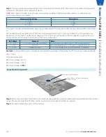
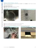
Страница 32: ...by turning quarter turn fasteners holding face in place NOTE Safety cables will be attached to the diffuser face but care should be taken to ensure that diffuser face does not swing and injure anyone...

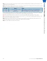
Страница 33: ...ch the filter media as it can damage the filter If your unit is 24 x 48 or 24 x 36 skip to Step 8 Step 5 Remove the 2 nuts securing the baffle retainer bracket using a 7 16 socket wrench Location of N...

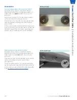
Страница 34: ...the control lid Step 9 Remove the control lid from the inside of the plenum using a 7 16 socket wrench for access to the control box Step 10 Reverse the previous steps taken to re assemble the unit Ba...

Страница 35: ...torque all that is required is to open the connection of the white wire as shown Switching from constant torque to constant flow To switch the motor from constant torque to constant flow all that is...

Страница 36: ...ity procedure outlined above 4 Conduct smoke and photometer test on HEPA ULPA filter Seal or replace Motor Keeps Shutting Off 1 Check if unit is ducted 2 If no contact Price at criticalenvironments pr...

Страница 37: ...ter 15 5x19 5x0 437 045964 004 MERV8 Pre filter 15 5x15 5x0 75 042313 055 MERV8 Pre filter 15 5x19 5x0 75 042313 043 Reverse Exhaust Flow PF 2x2 MERV8 Pre filter 19 5x19 5x0 75 042313 044 2x3 MERV8 Pr...

Страница 38: ...Transformer 019436 004 208 240V 20VA Transformer 019436 013 277V 20VA Transformer 019436 007 Disconnect Switch Single Pole 15 Amp 277V 115V w o PC Option 019903 001 Dual Pole 30 Amp 208 240V 115V w PC...

Страница 39: ...ocument contains the most current product information as of this printing For the most up to date product information please go to KeystoneCleanAir com 2022 Keystone Clean Air Solutions All rights res...

Отзывы: