background image

Installation Note N9010-90072

15

Option MTU and MTP, MultiTouch User Interface Upgrade Kits

Replacing CPU Assembly - N9010A-MTP Upgrade Only

The steps in this section apply only to N9010A-MTP upgrades, where the CPU is replaced. If the 

N9010A-MTU upgrade is being performed, skip to "

Replacing Solid State Drive (SSD) - 

N9010A-MTU Upgrade Only

". 

1.

Turn off the instrument and remove the AC power cord.

2.

Refer to 

Figure 5

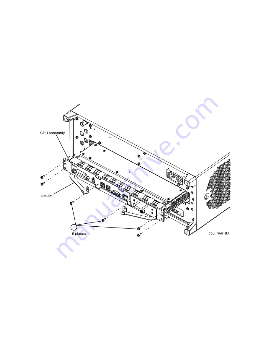
. Remove the existing CPU assembly from the instrument by removing the 6 

rear panel screws 

(1)

. The CPU assembly can be removed from the chassis by using the two 

ejectors to pull it straight out the back.

Figure 5 

CPU Assembly Removal

3.

With the ejectors pulled out, slide the new CPU assembly into the slot at the rear of the 

instrument and push on the assembly to mate the connectors. Gently secure the CPU 

assembly to the instrument with the ejectors.

4.

Replace the six screws 

(1)

 that attach the CPU assembly to the chassis. Torque to 

9 inch-pounds.

Содержание N9010AK-MTP

Страница 1: ...Option MTU MultiTouch User Interface Upgrade Kit Option MTP MultiTouch User Interface Upgrade Kit with PC7 CPU Keysight Technologies N9010A EXA Signal Analyzer Installation Note ...

Страница 2: ...d to the implied warranties of merchantability and fitness for a particular purpose Keysight Technologies shall not be liable for errors contained herein or for incidental or consequential damages in connection with the furnishing performance or use of this material Manual Part Number N9010 90072 Edition Edition 1 June 2016 Printed in USA Malaysia Published by Keysight Technologies Inc 1400 Founta...

Страница 3: ...010AK MTP should be installed on N9010As that do not have a PC6 or PC7 CPU A PC7 CPU is included in this kit along with a new SSD Part of the upgrade process is the license transformation process which creates new licenses to replace those of the existing measurement applications This is because older measurement application licenses whose model numbers end in the letters A or B for example N9071A...

Страница 4: ...9068C Phase Noise measurement application or the N9071C GSM EDGE measurement application If the current version of instrument software does not support one of the transformed licenses the description as displayed in the Show System screen will include the phrase Dormant License UI Conversion For example N9064A Dormant License UI Conversion VXA app The hardware included in the kit may come in sever...

Страница 5: ... Core Bracket Bottoma N9020 00072 1 Knob RPG Large W1312 40017 1 Solid State Drive Replacement WES7 3 Screws M3 x 0 5 8 mm long pan heada 0515 0372 9 Screws M3 x 0 5 8 mm long flat head 0515 2032 1 Nameplate 3 6 GHz MultiTouch N9010A N9010 80030 1 Nameplate 7 GHz MultiTouch N9010A N9010 80031 1 Nameplate 13 6 GHz MultiTouch N9010A N9010 80032 1 Nameplate 26 5 GHz MultiTouch N9010A N9010 80033 1 Na...

Страница 6: ...ual Core Celeron 8 GB RAM W1312 60210 1 Tray Assembly solid state drive 160 GB W1312 60302 9 Screws M3 x 0 5 8 mm long flat head 0515 2032 1 Nameplate 3 6 GHz MultiTouch N9010A N9010 80030 1 Nameplate 7 GHz MultiTouch N9010A N9010 80031 1 Nameplate 13 6 GHz MultiTouch N9010A N9010 80032 1 Nameplate 26 5 GHz MultiTouch N9010A N9010 80033 1 Nameplate 32 GHz MultiTouch N9010A N9010 80034 1 Nameplate ...

Страница 7: ... The instrument will probably display a spectrum analyzer screen and you will see the instrument sweeping There should be no alignment failures If there are failures investigate and fix the problem before continuing Before you disassemble the instrument turn the power switch to Standby After the instrument has completely shut down unplug the instrument Failure to unplug the instrument can result i...

Страница 8: ...er to the data in step 2 above If the Product Number is not N9010A do not proceed with the installation of this kit This kit is to be installed only on N9010A signal analyzers 5 Refer to the data in step 3 above If upgrade product N9010A MTU is being installed and the currently installed CPU is either N9010A PC1 N9010A PC2 N9010A PC3 N9010A PC4 or N9010A PC5 do not proceed with the installation of...

Страница 9: ...e Licenses_N9010A_MY50060101 4 Insert the USB storage device into one of the analyzer s USB ports 5 Using the mouse navigate to the folder C Program Files Agilent licensing 6 Change the folder s properties so that hidden files can be viewed a If the operating system is WinXP click on Tools and select Folder Options Select the View tab In the Advanced Settings window under Hidden files and folders ...

Страница 10: ...instrument software version that was recorded in the Analyzer Information section step 2 of this document and follow the steps outlined below for that version S W Revision Less Than A 01 55 Instruments with a software version older than A 01 55 will first need to have the software updated to the latest version prior to being able to backup the instrument calibration data See the Software Updates s...

Страница 11: ...ll appear Figure 1 Calibration Data Backup 6 Under the Specify Backup Folder or File Name use the mouse to select the button to open the Browse For Folder dialog box 7 Select the USB memory device and press OK 8 Select Backup and wait for confirmation that the calibration database has been backed up 9 When the backup has completed close the Calibration Data Backup And Restore window The file will ...

Страница 12: ...t it into one of the available instrument USB ports Perform a virus scan on this device before use 3 On the front panel of the instrument press System Alignments Backup or Restore Align Data Click on OK The signal analyzer application will close and the Alignment Data Wizard will start This might take a few minutes 4 The Alignment Data Wizard window as shown in Figure 2 will appear Figure 2 Alignm...

Страница 13: ...MTU upgrades where the solid state drive is replaced If the N9010A MTP upgrade is being performed skip to Replacing CPU Assembly N9010A MTP Upgrade Only 1 Turn off the instrument and remove the AC power cord 2 Refer to Figure 3 Locate and remove the existing disk drive carrier assembly 2 from the instrument by loosening the rear panel screw 1 Figure 3 Replacing the Disk Drive Carrier Assembly ...

Страница 14: ...rier assembly that secure the drive 2 Figure 4 Disk Drive Screws 4 Remove the disk drive 2 from the carrier assembly 5 Place the new disk drive included in the kit onto the carrier assembly and attach with the four machine screws 1 Torque to 9 in lbs 6 Refer to Figure 3 Replace the disk drive carrier assembly 2 into the instrument and tighten the screw to 9 in lbs ...

Страница 15: ... AC power cord 2 Refer to Figure 5 Remove the existing CPU assembly from the instrument by removing the 6 rear panel screws 1 The CPU assembly can be removed from the chassis by using the two ejectors to pull it straight out the back Figure 5 CPU Assembly Removal 3 With the ejectors pulled out slide the new CPU assembly into the slot at the rear of the instrument and push on the assembly to mate t...

Страница 16: ...by a screen that automatically loads the operating system 4 The License Agreement dialog box as shown in Figure 6 appears providing information regarding the instrument software licensing During the initial power on process the instrument may turn itself off and restart a number of times This is normal and only happens during the initial installation process The instrument may require more than 5 ...

Страница 17: ...tware 5 After the instrument restarts a status window as shown in Figure 7 appears providing information regarding the instrument software licensing Figure 7 Application Launch Status Window After launching the setup do not turn off the instrument or remove power before the setup routine completes and the system restarts Turning off the instrument may corrupt the system and the instrument software...

Страница 18: ...9 Continued Application Launch Status Window 9 Once the instrument application software completes loading the instrument initialization will be completed Continue with the next section for putting the new disk drive or CPU into service If you do not check the Do not show this message again check box this message will be displayed each time the instrument is turned on No application will start whil...

Страница 19: ...elected license key files 5 Navigate to the C Program Files Agilent licensing folder 6 Press Ctrl V to copy all the license key files to the licensing folder 7 As each license is installed you will see a message saying Successful License Installation in the lower right corner of the instrument display 8 If you see a Feature Already Licensed message for each of the licenses being restored in the lo...

Страница 20: ...W Revision Updating the Instrument Software 1 Compare the currently installed software version with the original software version noted in step 2 of the Analyzer Information procedure earlier in this note 2 If the original software version noted in step 2 of the Analyzer Information procedure is newer than the currently installed software version an instrument software update is required The lates...

Страница 21: ...ith the instrument or run an FGPA update program If this program detects that there are assemblies that need to be updated it will update them to the correct version Updating the Instrument FPGA Code 1 Connect a USB mouse and keyboard to available instrument USB ports 2 Using the mouse select Start My Computer Navigate to the following folder C Program Files Agilent SignalAnalysis Physics 3 In thi...

Страница 22: ...de Kits 5 To program the FPGA code enter 1 and press Enter You will need to confirm this selection by selecting 1 and Enter one more time 6 The programming of the FPGA code could take a few minutes to complete Once it has finished the instrument will reboot itself to use the new code ...

Страница 23: ...earlier used to backup the instrument calibration data to one of the instrument USB ports 3 Press System Alignments Backup or Restore Align Data 4 The Alignment Data Wizard window as shown in Figure 2 will appear 5 Follow the on screen instruction to Restore the calibration data from the USB memory device No matter how the instrument calibration data was backed up prior to this upgrade any further...

Страница 24: ...p should be performed this time to the SD card 1 Remove any USB memory devices from the instrument 2 With the instrument turned on and the signal analyzer application running as normal press System Alignments Backup or Restore Align Data 3 The Alignment Data Wizard window as shown in Figure 11 will appear Figure 11 Alignment Data Wizard 4 Follow the on screen instructions to backup the calibration...

Страница 25: ...he new licenses the analyzer has a 100 license limit To delete the currently installed licenses for which migration products exist proceed as follows a With a keyboard and mouse connected to the USB ports of the analyzer close the XSA application b Click on Start All Programs Keysight License Manager Keysight License Manager This will launch the Keysight License Manager which will list all current...

Страница 26: ...es When the License File is consumed the Keysight License Manager will display a Successful License Installation message similar to the one shown in Figure 13 Since the license file contains multiple licenses multiple Successful License Installation messages will appear Wait until all licenses have been consumed before removing the USB Storage Device Figure 13 Successful License Installation Verif...

Страница 27: ...ts face during any of the following procedures be sure to use a soft surface or soft cloth to avoid damage to the front panel keys or input connector If the analyzer has Option PRC Portable Configuration refer to the Portable Instrument Option PRC section on page 29 to remove the outer case Make sure any adapters on the front panel are removed ...

Страница 28: ...0 driver remove the four screws two on each side 1 that attach the handle strap 2 on each side of the instrument 3 Using the T 20 driver remove the four screws including washers 3 that hold the rear feet 4 in place 4 Pull the instrument cover 5 off towards the rear of the instrument Figure 14 Standard Instrument Outer Case Removal 5 Proceed to the Front Frame Assembly Removal section to remove the...

Страница 29: ...ach side 1 that hold the bail handle 2 to the front frame Figure 15 Bail Handle Removal 3 Using the T 20 driver remove the screws 3 which secure the four front bumpers 4 to the front frame assembly These screws and bumpers will be re installed on the new front frame assembly 4 Using the T 20 driver remove the four screws two on each side 6 that hold the strap handle plugs 5 in place Make sure any ...

Страница 30: ...r Interface Upgrade Kits 5 Refer to Figure 16 Using the T 20 driver remove the four screws including washers 1 that hold the rear bumpers 2 in place 6 Pull the instrument cover 3 off towards the rear of the instrument Figure 16 Option PRC Instrument Outer Case Removal ...

Страница 31: ...bly Removal 1 If the EXA has Option EXM External Mixer use a open end wrench and 5 16 open end wrench to disconnect semi rigid coax cable W27 from W28 2 Refer to Figure 17 Using the T 10 driver remove the eight screws 1 four on each side to detach the front frame from the chassis Figure 17 Front Frame Removal ...

Страница 32: ...fully away from the chassis Remove the ribbon cable W1 from the A8 Motherboard Figure 18 Front Panel Cable 4 Pull the Front Frame Assembly carefully away from the chassis Remove the ribbon cable W1 from the motherboard W1 may have locking springs on each side Depress the spring on each side of the connector to remove from the motherboard ...

Страница 33: ... External Mixing Parts from Original Front Frame 1 Refer to Figure 19 Disconnect semi rigid coax cable W27 from the Ext Mixer connector using a 5 16 inch open end wrench W27 will be re used Figure 19 Disconnect W27 from Ext Mixer Connector This procedure applies only to instruments with Option EXM External Mixing ...

Страница 34: ...ure 20 Use a deep 5 16 inch socket wrench to loosen and remove the hex nut 2950 0223 and lock washer 2190 0067 on the inside of the front frame that is attaching the Ext Mixer connector to the front frame The Ext Mixer connector lock washer and hex nut will be re used Figure 20 Removing EXT MIXER Connector ...

Страница 35: ...cy range option of either 532 or 544 choose Overlay Keypad N9020 80165 3 Ensure that the front frame around the keypad is clean 4 Remove the backing from the Keypad Overlay and carefully apply it to the new Front Frame Assembly Press down on the Keypad Overlay to ensure good adhesion to the Front Frame Assembly 5 Locate the Knob W1312 40017 in the kit Push the knob onto the shaft of the RPG 6 Loca...

Страница 36: ...the assembly The hex feature on the connector should engage with the recess in the front frame assembly Refer to Figure 21 Secure the connector using the lock washer and hex nut from the rear Torque to 21 inch pounds Figure 21 Attaching SMA Female Connector 3 Locate the External Mixing Front Panel semi rigid coax assembly that was removed from the original front frame assembly This is W27 Note tha...

Страница 37: ...t W27 so that the cable slopes upward from the Ext Mixer connector at a 15 degree angle The top of the connector should be approximately level with the top of the shield over the Front Panel Interface board Refer to Figure 23 Torque the cable nut on the Ext Mixer connector to 10 inch pounds Figure 22 Connecting W27 to Ext Mixer Connector Figure 23 Proper Orientation of W27 ...

Страница 38: ...ser Interface Upgrade Kits New Front Frame Installation 1 Refer to Figure 24 Reattach the ribbon cable W1 Ensure the locking tabs are engaged 2 Carefully install the front panel assembly making sure that the ribbon cables are not pinched Figure 24 Front Panel Cable ...

Страница 39: ...e Upgrade Kits 3 Refer to Figure 25 Carefully position the Front Frame Assembly onto the chassis Ensure no cables are crushed Secure with the eight screws 0515 2032 1 included in the kit four on each side of the chassis Torque to 9 inch pounds Figure 25 Front Frame Installation ...

Страница 40: ...t installed skip steps 5 through 7 5 Refer to Figure 26 When the front panel is installed cables W27 and W28 typically do not align This is OK since the cables are flexible 6 Refer to Figure 27 Align and connect cables W27 and W28 Hand tighten the nut Figure 26 W27 and W28 Before Alignment Figure 27 W27 and W28 Properly Aligned ...

Страница 41: ...m twisting Use a 5 16 torque wrench to torque the nut on W27 to 10 inch pounds Figure 28 Torque Cable W28 onto W27 8 If Option EXM External Mixing is not installed and the Keypad Overlay which accommodates Opt EXM N9020 80165 is installed locate the black hole plug 6960 0076 in the kit Insert the hole plug in the EXT MIXER port opening in the upper right corner of the front panel ...

Страница 42: ...zer has Option EXM External Mixer locate the 50 Ω termination 1810 0118 that was removed earlier Connect the 50 Ω termination to the EXT MIXER connector Final Installation for Portable Instruments Option PRC Figure 15 and Figure 16 1 Refer to Figure 16 Carefully slide the instrument cover back onto the instrument from the rear of the analyzer making sure not to damage any internal cables The seam ...

Страница 43: ...d All if the Calibration data file could not be backed up and restored None if the Calibration data file was backed up and restored A full calibration is required to assure the instrument meets all specifications For assistance contact your nearest Keysight Technologies Sales and Service Office To find your local Keysight office access the following URL or if in the United States call the followin...

Страница 44: ...This information is subject to change without notice Keysight Technologies 2016 Edition 1 June 2016 N9010 90072 www keysight com ...

Отзывы: