


8
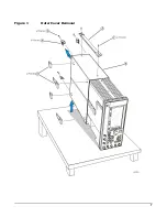
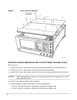
Figure 2
Inner Top Cover Removal
Remove Front Panel (Instruments with Front RF Output Connectors Only)
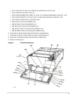
1. Using the T-10 driver, remove the four screws from the Baseband Generator cover (E8267D only).
2. Using the T-15 driver, remove the six screws (1) from the sides of the frame.
3. Using the T-10 driver, remove one screw from the top (2) and one screw from bottom (3) of the frame.
CAUTION
Before removing the front panel from the signal generator, lift and support the front of the
signal generator’s frame.
4. Slide the front panel over the RF output connector.
5. Using the needle-nose pliers, disconnect the following flexible cables:
• W1 (EXT 1 INPUT) from the A11 Pulse/Analog Modulation Generator J401.
• W2 (EXT 2 INPUT) from the A11 Pulse/Analog Modulation Generator J402.
Содержание E8251-60386
Страница 7: ...7 Figure 1 Outer Cover Removal ...


