


10
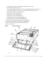
Install Option 1ED (Instruments with Front RF Output Connectors)
1. Using the 5/6” open-wrench, remove the semi-rigid cable connected to the RF output connector.
2. Using the T-10 driver, remove the screw securing the connector to the instrument. The screw is on the
outside edge of the connector.
3. Remove the old RF Output connector.
4. Install the Option 1ED Type-N connector by reversing the removal process, steps 1 and 2.
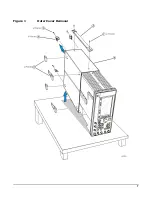
5. Reinstall the front panel by reversing the order of removal, see
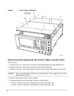
Install Option 1ED (Instruments with Rear RF Output Connectors)
1. Using the 5/6” open-wrench, remove the semi-rigid cable connected to the RF output connector.
2. Using the T-10 driver, remove the two screws securing the connector to the rear panel of the instrument.
3. Remove the old RF Output connector.
4. Install the Option 1ED Type-N connector by reversing the removal process, steps 1 and 2.
Re-Assemble the Signal Generator
1. Reinstall the inner and outer instrument covers by reversing the order for removal.
2. Torque all T-10 screws to 9 in-lbs.
3. Torque all T-15 and T-20 screws to 21 in-lbs.
Verify Signal Generator Calibration
1. Turn the signal generator on and allow it to warm up for 30 minutes.
2. Perform the following adjustment and performance tests to verify signal generator calibration. Refer to
the PSG Family Signal Generators Service Software:
• Power Flatness Calibration
• Self Tests
• Maximum Leveled Output Power
• Power Level Accuracy
Содержание E8251-60386
Страница 7: ...7 Figure 1 Outer Cover Removal ...


