


2 Performance Verification
18
Series E4360 Service Guide
5
Divide the voltage drop (DMM reading) across the current shunt by
the shunt resistance to convert to amperes and record this value
(Iout). Also, record the current reading measured over the interface.
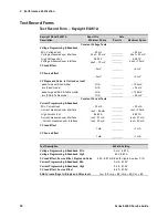
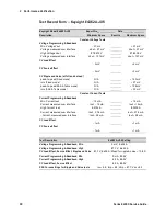
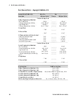
The readings should be within the limits specified in the test record
form under “Current Programming and Readback, High Current”.
Current Sink Readback
Test category = performance
This test verifies current sink operation and readback.
1
Turn off the solar array simulator and connect the output as shown
in Test Setup figure B, except connect a DC power supply in place of
the electronic load. The polarity of the power supply should be the
same as the electronic load.
2
Set the external power supply to 5 V and its current limit to 20% of
the full scale current value of the output under test.
3
Turn on the solar array simulator and program the output voltage to
zero. The current on the display should be approximately 0.42 A
(0.32 A for E4361A-J11).
4
Divide the voltage drop across the current monitoring resistor by its
resistance to obtain the current sink value in amps and subtract this
from the current reading on the display. The difference between the
readings should be within the limits specified in the Performance
Test Record Form under “–Current measured over interface.”
CC Load Effect
Test category = performance
This test measures the change in output current resulting from a change
in output voltage from full scale to short circuit.
1
Turn off the solar array simulator and connect the current shunt,
DMM, and electronic load (see Test Setup figure B). Connect the
DMM directly across the current shunt.
2
Turn on the solar array simulator and program the instrument as
indicated in the test record form under “CC Load Effect”.
3
Set the electronic load for CV mode and program it to the output
channel’s voltage as described in the test record form under “CC
Load Effect”. The CC annunciator on the front panel must be on. If
not, adjust the load so that the output voltage drops slightly.
4
Divide the voltage drop (DMM reading) across the current
monitoring resistor by its resistance to convert to amperes and
record this value (Iout).
5
Short the electronic load. Divide the voltage drop (DMM reading)
across the current monitoring resistor by its resistance to convert to
amperes and record this value (Iout). The difference in the current
readings in steps 4 and 5 is the load effect, which should not exceed
the value listed in the test record form under “CC Load Effect”.
Содержание E4360 Series
Страница 1: ...Service Guide Keysight Technologies Series E4360 Modular Solar Array Simulator ...
Страница 2: ......
Страница 6: ......
Страница 10: ......
Страница 40: ......
Страница 44: ...4 Disassembly 44 Series E4360 Service Guide ...
Страница 64: ......
Страница 72: ......